
Vertebral spacer

a technology of vertebrae and spacers, applied in the field of surgery, can solve the problems of inability to properly position the parts of the vertebrae, high manufacturing cost, and inability to achieve the effect of a simple and robust construction, precise and controlled adjustment of the opening

Active Publication Date: 2020-09-24
NIMESIS TECH +2
View PDF0 Cites 0 Cited by
  • Summary
  • Abstract
  • Description
  • Claims
  • Application Information

AI Technical Summary

Benefits of technology

The present invention provides a simple and robust spacer for implantation in a patient's vertebral body, which allows for controlled displacement of the vertebral plates regarding both amplitude and direction. This spacer is easy to position and use, and can be used for different treatments of anterior and posterior fractures. It has a small size, making it easy to introduce into a patient's vertebral body through a small tube. The temporary position of the spacer can be easily re-positioned before the injection of the consolidation material. Most importantly, this spacer allows for precise and controlled adjustment of the opening, which is difficult with other spacers.

Problems solved by technology

Given the size of the components of these spacers and the size of the vertebrae in which these spacers are introduced, the realization of these mini jacks is extremely delicate.
This generates high manufacturing costs.
They are then no longer able to position the parts of the vertebra adequately and / or they deform.
More generally, it is difficult to position these jacks correctly.
Once they are placed in the vertebra, it is no longer possible to change their position.
Thus, it is difficult to control the displacement of the vertebral plates, meaning that such displacement is generally not optimal.
Moreover, a substantial force is required to properly position the vertebral plates.
Small jacks are not suitable in the presence of such forces and the risk of breakage of some parts cannot be excluded.
As a result, it is not possible to move the plates of the vertebra into a chosen position.
These different spacers do not allow for a force to be applied in a chosen direction, neither is their construction simple or robust.

Method used


Image

  • Vertebral spacer
  • Vertebral spacer
  • Vertebral spacer

Examples


Embodiment Construction

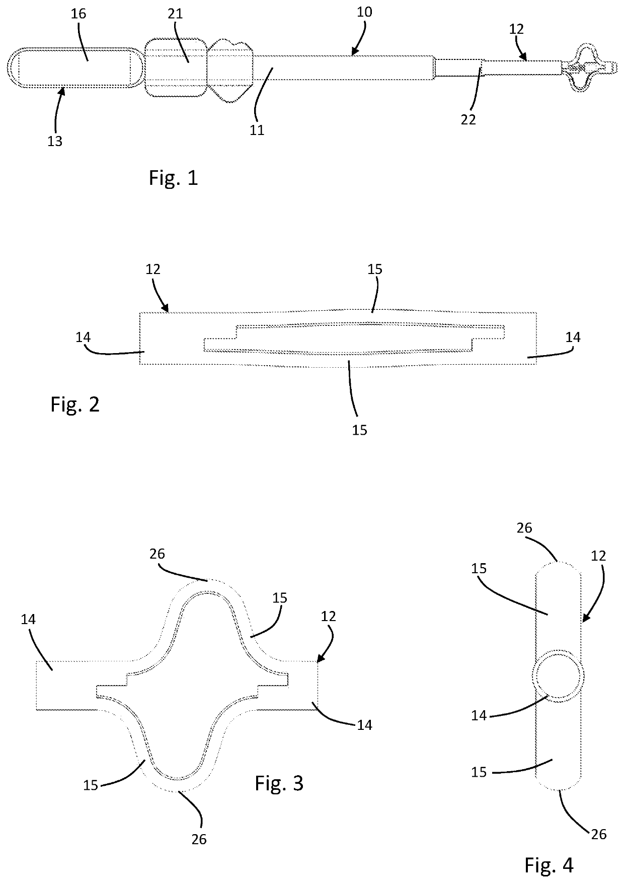
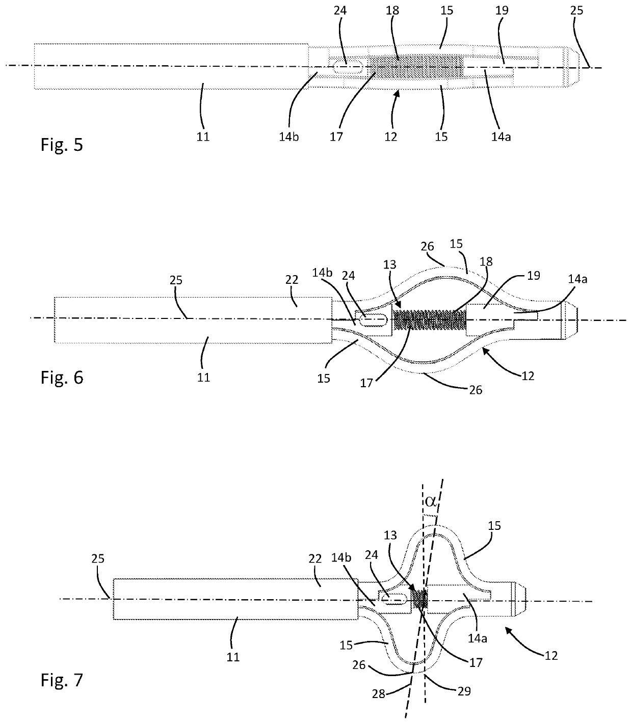
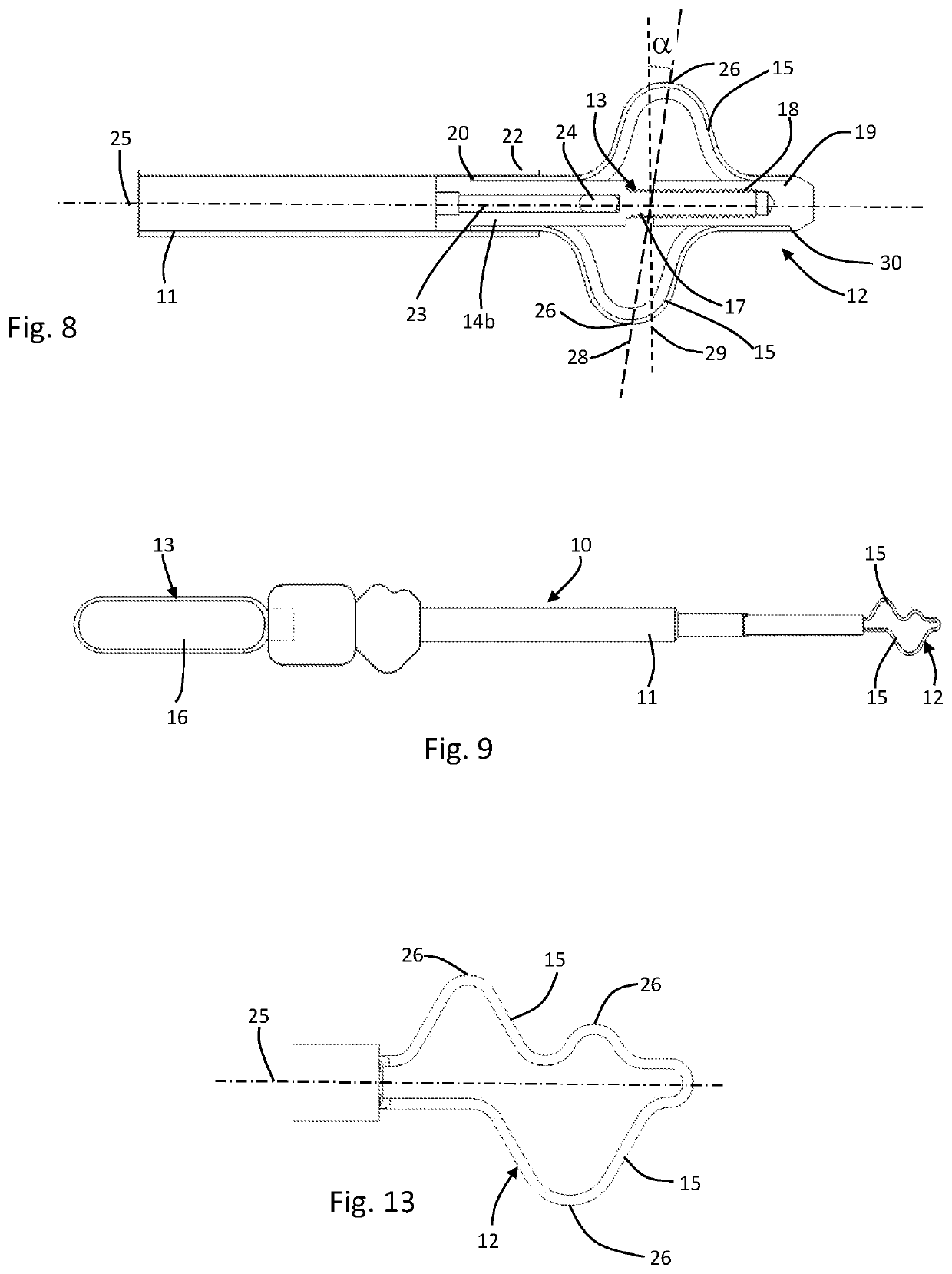
[0033]With reference to the drawings, the spacer 10 according to the present invention essentially comprises a tube 11, a spacer module 12 and an actuating system 13 of the spacer module.

[0034]In general, the spacer module 12 and the actuating system 13 are arranged at least partially within the tube 11. The actuating system 13, when actuated, is configured to move the spacer module 12 when the tube 11 is placed in a patient who has to undergo a vertebroplasty operation. This actuating system 13 can be actuated from outside of the patient's body and acts on the spacer module 12 which is inside the patient's body.

[0035]Referring to FIGS. 1 to 8, corresponding to a first embodiment of the spacer of the invention, the spacer module 12 according to the present invention has a substantially tubular shape. This spacer module 12 comprises a holding zone 14 at each of its ends and two blades 15 integral with these holding zones 14. The holding zone farthest from the end of the tube remainin...


PUM


Abstract

The present invention relates to a spacer intended to be introduced between two elements of a vertebral body. This spacer comprises a tube, a spacer module and an actuating system of the spacer module, the actuating system comprising at least one rod which is, on one hand, accessible from a distal end of the tube and, on the other hand, connected to said spacer module. The spacer is characterized in that the spacer module comprises two blades coplanar to a longitudinal axis of the rod, these blades being movable between a closed position in which the blades are substantially parallel to the longitudinal axis of the rod, and a deployed position in which the blades have an arched shape, and in that in their deployed position, these blades are asymmetrical with respect to each other and with respect to said longitudinal axis of the rod.

Description

TECHNICAL FIELD[0001]The present invention relates generally to the field of surgery and applies in particular to the field of reconstructive surgery for vertebral fractures or for vertebroplasty.[0002]In more detail, this invention relates to a spacer for insertion into the vertebral body of a patient. In particular, this spacer is intended to be introduced between two parts of a vertebra and in particular between two parts of a fractured or otherwise defective vertebra.BACKGROUND ART[0003]Vertebral fractures are a relatively common condition that can occur as a result of a fall or an accident, but in most cases occur as a result of osteoporosis.[0004]One way to treat these fractures is the use of vertebroplasty or kyphoplasty. This technique consists in injecting a consolidation material such as a resin, an acrylic cement or, more generally, a biocompatible fluid material, hardening after injection, into the fractured or defective vertebra in order to consolidate it. Before the in...

Claims


Application Information

Patent Timeline
Patent Type & Authority Applications(United States)
IPC IPC(8): A61F2/44
CPCA61F2002/443A61F2/4425A61F2002/30092A61F2002/30433A61F2002/30476A61B17/8858
Inventor HAUTCOEUR, ALAINFOUCHE, FLORIAN
Owner NIMESIS TECH
Learn More