Check patentability & draft patents in minutes with Patsnap Eureka AI!

Magnetoelastic based sensor assembly

a sensor and magnetoelastic technology, applied in the direction of instruments, force/torque/work measurement apparatus, vehicle tractive/propulsive power measurement, etc., can solve the problems of complex measurement and control device, high cost of sensor assembly, and often structural weakening of load conducting elements, etc., to achieve the effect of measuring stress and strain

Active Publication Date: 2020-09-24
METHODE ELECTRONICS MALTA
View PDF0 Cites 0 Cited by
  • Summary
  • Abstract
  • Description
  • Claims
  • Application Information

AI Technical Summary

Benefits of technology

The invention is an improved sensor that can measure stress and strain in systems that are subject to mechanical loads. It also provides a way to determine which direction the load is coming from.

Problems solved by technology

However, strain gauges often require a structural weakening of the load conducting elements.
Prior art load measurement devices for tow couplings have significant shortcomings, e.g. the complexity of the measurement and control devices, and the costs of the sensor assembly.

Method used


Image

  • Magnetoelastic based sensor assembly
  • Magnetoelastic based sensor assembly
  • Magnetoelastic based sensor assembly

Examples


Embodiment Construction

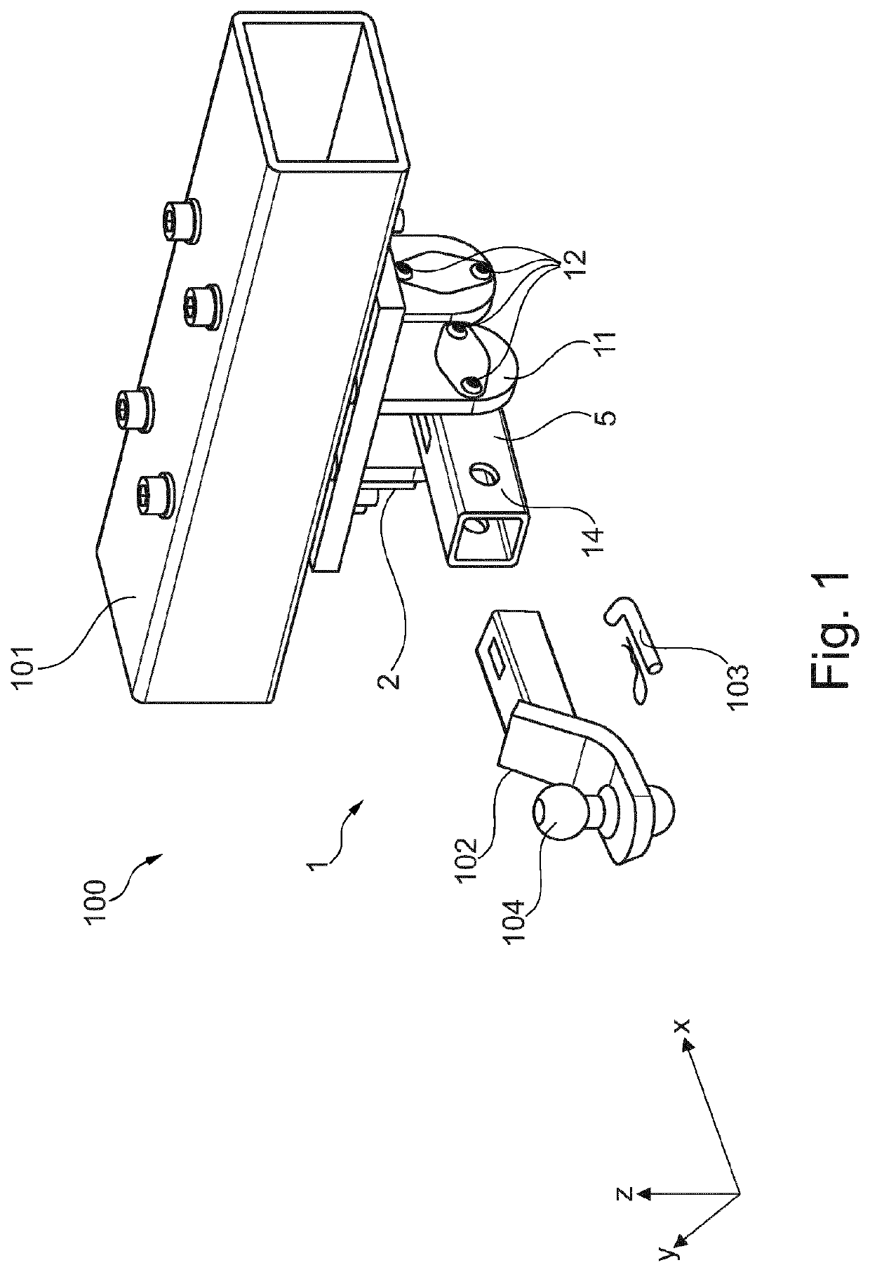
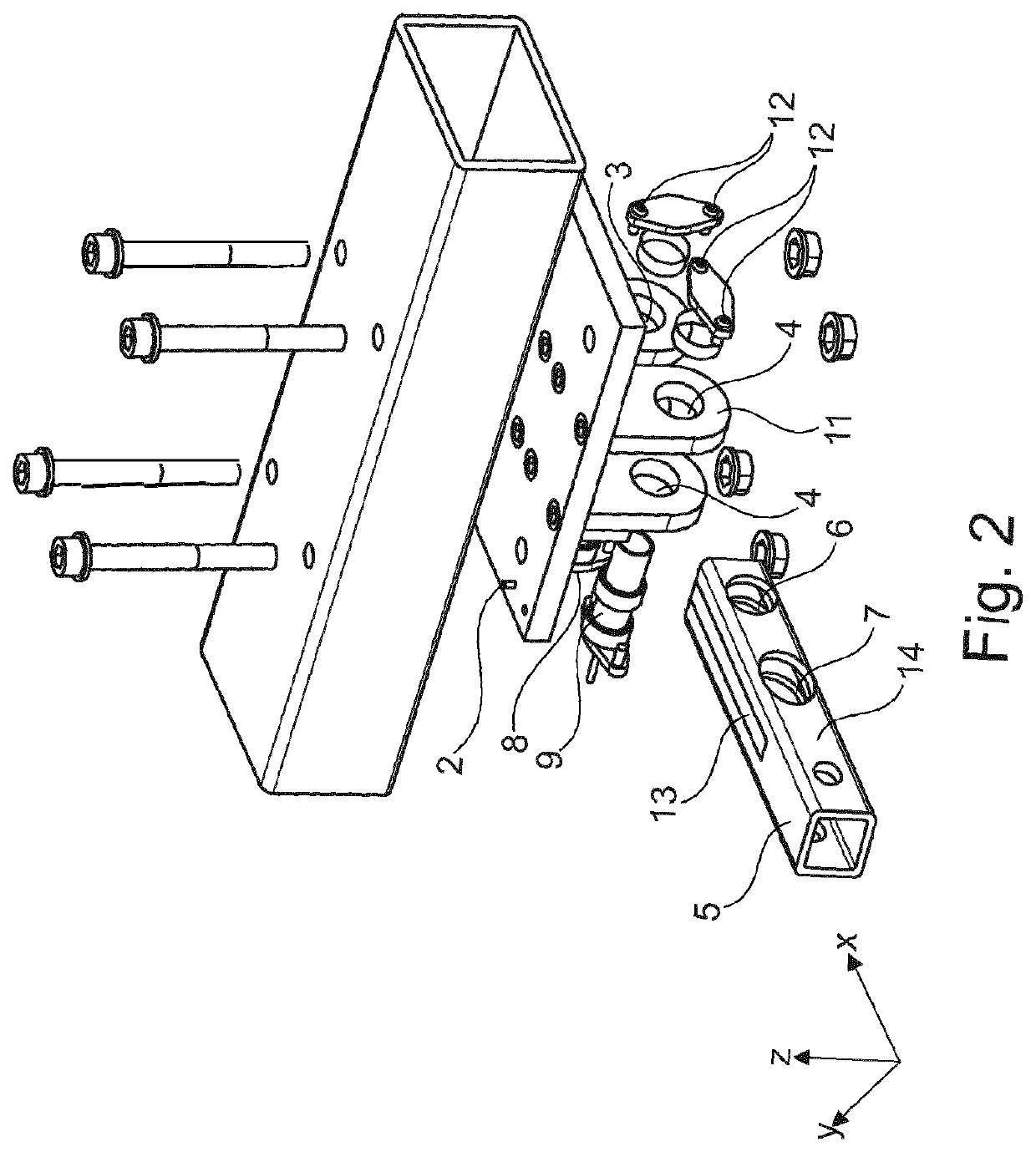
[0057]FIG. 1 is a simplified perspective view of a tow coupling comprising a sensor assembly 1 for force sensing according to aspects of the invention; FIG. 2 is a simplified exploded view of the tow coupling.

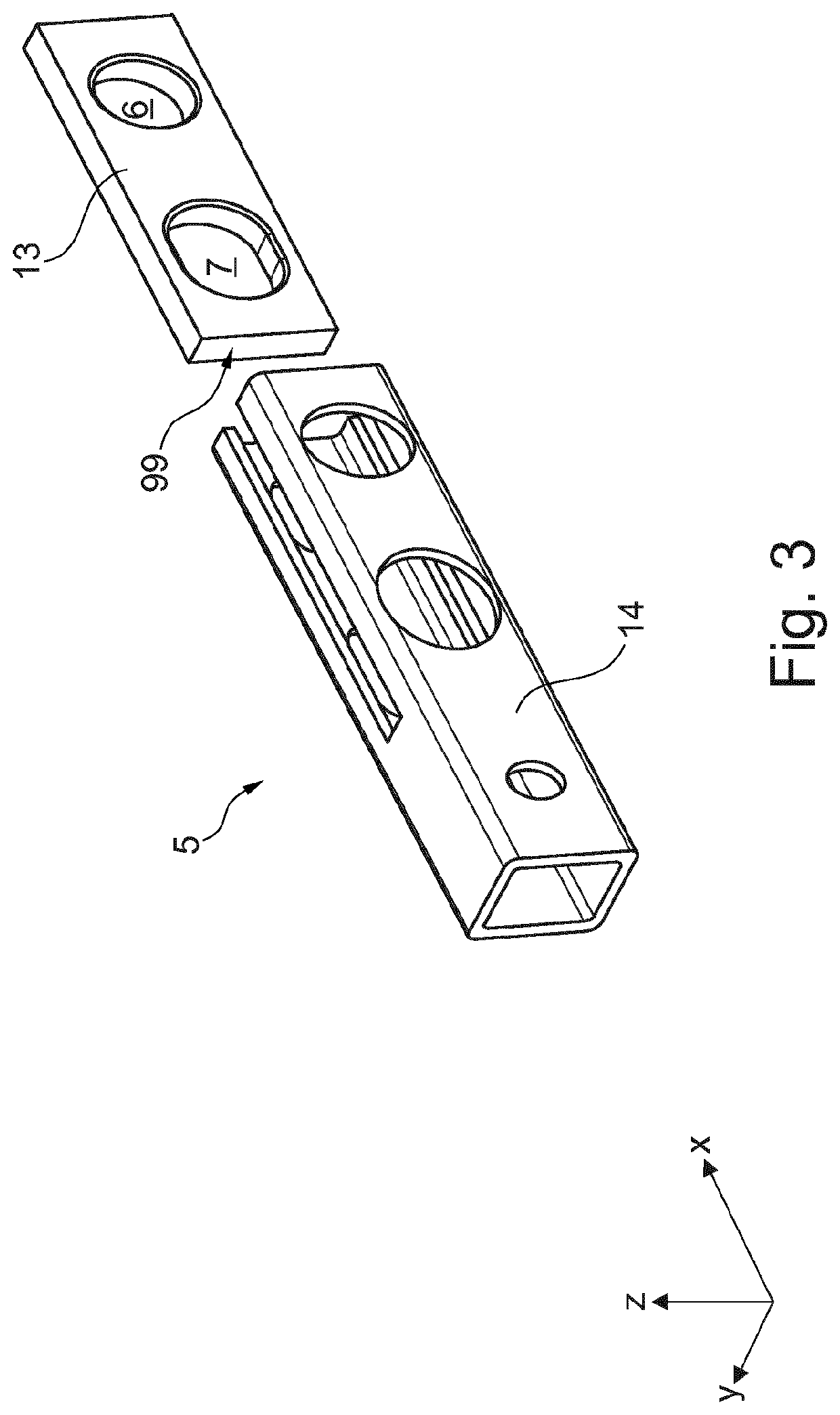
[0058]The sensor assembly 1 for force sensing comprises a first portion 2 (supporting yoke) having a first through hole 3 and a second through hole 4, a second portion 5 (receiving tube) having a third through hole 6 and fourth through hole 7. The third and fourth through holes 6, 7 are positioned in correspondence to the first and second through holes 3, 4.

[0059]The second portion defines a Cartesian coordinate system having a longitudinal direction X, a transversal direction Y and a vertical direction Z. The longitudinal direction X extends in the direction of longitudinal extension of the second portion. The transversal direction Y extends in a direction perpendicular to the longitudinal direction X and in a horizontal plane. The vertical direction Z extends in a direction t...


PUM


Abstract

The invention provides a sensor assembly for force sensing, the sensor assembly comprising: a first portion having a first and a second through hole, a second portion having a third and fourth through hole, and a first pin and a second pin coupling the first portion to the second portion. At least one out of the first and the second pin comprises a magnetoelastic based sensor for outputting a signal corresponding to a stress-induced magnetic flux emanating from a magnetically polarized region of the pin. The magnetoelastic based sensor comprises at least one direction sensitive magnetic field sensor in an at least partially hollow portion of the pin, which field sensor is configured for determination of a shear force in at least one direction. The invention further provides a tow coupling comprising the sensor assembly. The invention further provides a method for detecting a load.

Description

CROSS-REFERENCE TO RELATED APPLICATIONS[0001]This is a continuation application of, and which claims the benefit of the filing date and disclosure of, U.S. patent application Ser. No. 16 / 523,418, filed on Jul. 26, 2019, entitled “Magnetoelastic Based Sensor Assembly,” which is a continuation of and claims the benefit of the filing date of International Application PCT / EP2018 / 000105, filed Mar. 22, 2018, which is based on and claims the benefit of the filing date of European Patent Application No. 17162429.9, filed on Mar. 22, 2017, the contents of each of which are incorporated by reference herein.BACKGROUND OF THE INVENTIONField of Invention[0002]The invention is related in general to systems and methods involving the use of magnetic field sensors for measuring a load. In particular, the invention relates to a magnetoelastic based sensor assembly, i.e. a sensor assembly comprising a magneto-elastically active region and a tow coupling incorporating this sensor assembly. Furthermore...

Claims


Application Information

Patent Timeline
IPC IPC(8): B60D1/24B60D1/64G01L5/00G01L5/13
CPCG01L5/0004B60D1/64G01L5/136F16C11/06B60D1/248B60D1/04B60D1/52B60D1/62G01L5/169G01L5/16G01L1/125
Inventor GIESSIBL, JOHANNES
Owner METHODE ELECTRONICS MALTA
Features
  • R&D
  • Intellectual Property
  • Life Sciences
  • Materials
  • Tech Scout
  • Unparalleled Data Quality
  • Higher Quality Content
  • 60% Fewer Hallucinations
Learn More