Check patentability & draft patents in minutes with Patsnap Eureka AI!

Method for Filling a Nautical Hydraulic Steering System

a technology of hydraulic steering system and nautical steering system, which is applied in the direction of steering rudder, vessel construction, marine propulsion, etc., can solve the problems of messy and inability to do the manual process alon

Active Publication Date: 2020-09-24
OUTBOARD SPECIALTY TOOLS LLC
View PDF3 Cites 0 Cited by
  • Summary
  • Abstract
  • Description
  • Claims
  • Application Information

AI Technical Summary

Benefits of technology

The system allows for efficient and clean filling and purging of hydraulic oil in boat steering systems, reducing the need for manual effort and costly powered devices, while preventing spills and ensuring a closed system operation.

Problems solved by technology

Additionally, small leaks are common (hydraulic oil does not evaporate and is not consumed by use, so low levels of hydraulic oil are typically due to dry rotted or ruptured seals causing leaks), requiring additional hydraulic oil be added even when a complete flush is unnecessary.
The manual process cannot be done alone and is messy, requiring a stream of hydraulic oil to leave the bleeder into (hopefully) an appropriately placed bucket.
Although the powered device solves many of the issues involved with the manual device, it is expensive, costing about $750 from most online retailers.

Method used


Image

  • Method for Filling a Nautical Hydraulic Steering System
  • Method for Filling a Nautical Hydraulic Steering System
  • Method for Filling a Nautical Hydraulic Steering System

Examples


first embodiment

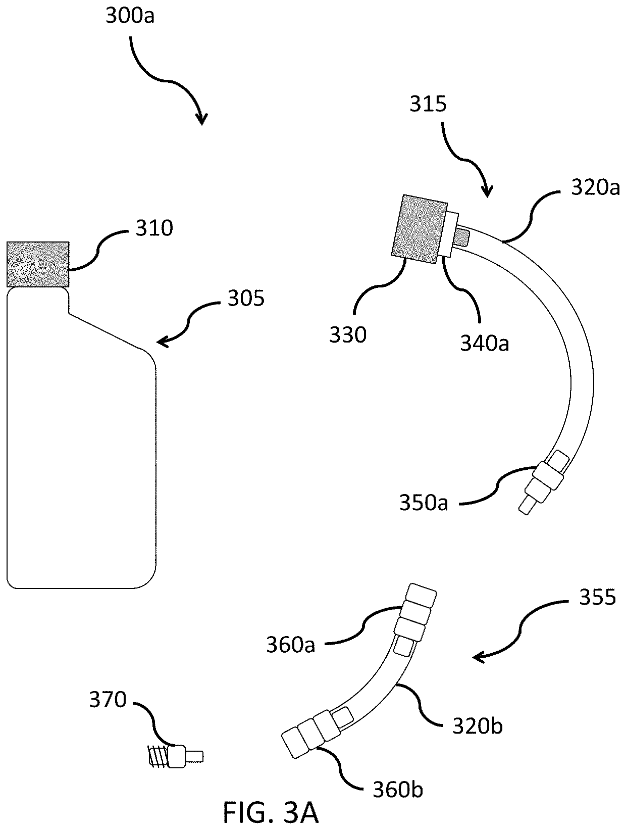
[0023]FIG. 3A is a depiction of helm-side components 300a of the system for filling hydraulic oil from nautical steering systems. The components 300a include a bottle of hydraulic oil 305, a bottle attachment 315a, a fluid lock 355, and a helm fill port adapter 370. The bottle of hydraulic oil 305 has a lid 310. The bottle attachment 315a includes a lid adapter 330, which is secured to the first hose 320a by a fastener 340a on one end, and a valve 350a on the other. The fluid lock 355 is a second hose 320b with corresponding valves 360a, 360b on both sides.

[0024]In the depicted embodiment, the lid adapter 330 is an injection-molded lid designed to conform to the dimensions of the bottle lid 310 that includes an 8 mm outside diameter spout in its center. The hoses 320a, 320b, 320c are a transparent polyurethane pneumatic tubing with a 12 mm outside diameter and an 8 mm inside diameter. The fastener 340a is an Oetiker® ear clamp, and the valve 350a is a male Parker® 21 KA series quick...

second embodiment

[0028]FIG. 3B is a depiction of helm-side components 300b of the system for filling hydraulic oil from nautical steering systems. The components 300b include the bottle of hydraulic oil 305, a bottle attachment 316, a fluid lock 356, and the helm fill port adapter 370.

[0029]The bottle attachment 316 can be a cap 380 with a valve 390. The cap 380 is designed to conform to the dimensions of the bottle lid 310. The cap 380 can be made out of brass and have a ⅛″ National Pipe Tapered tap. The valve 390 can be a rectus Parker® 21KA female quick connect with a male ⅛″ National Pipe Tapered thread. The valve 390 is inserted into the tap of the brass cap 380 (shown in FIG. 3B with dashed lines).

[0030]The fluid lock 356 is a hose 320c with two valves 350b, 360c. The hose 320c is optimally long enough so that the bottle 305 can rest on top of the helm 200. The valve 350c that connects with the bottle attachment 316 can be a male Parker® 21KA series quick connect coupling that, if it does not ...


PUM


Abstract

A method to fill hydraulic oil in hydraulic steering systems for boats. The method uses a closed system to reduce mess and waste, but does not require power and can be performed by a single operator. A bleed lock is secured to a ram's bleeders and hydraulic oil fed to a helm. By rotating a boat's steering wheel and moving the motor, air will flow out of the system into the bottle and hydraulic oil will flow into the system.

Description

FIELD OF THE INVENTION[0001]The present invention relates to hydraulic steering systems for boats.BRIEF DISCUSSION OF RELATED ART[0002]Hydraulic steering systems offer larger or high-powered vessels a smooth, lightweight feel when turning the steering wheel.[0003]Hydraulic steering is made up of three components: a pump with a reservoir for hydraulic oil, a ram that connects to a rudder or outboard engine, and connecting hoses that transmit pressurized fluid from the steering pump to a steering piston rod. Turning the steering wheel in either direction pumps oil through the lines to the ram, which in turn pulls or pushes the rudder, outboard, or sterndrive in the desired direction.[0004]The simplest example of hydraulic steering is found on small powerboats powered by single outboard or multiple engines linked by a tie bar. On a small boat, a compact hydraulic pump with integral hydraulic-fluid reservoir located at the steering wheel uses hoses to connect to a steering ram at a tran...

Claims


Application Information

Patent Timeline
Patent Type & Authority Applications(United States)
IPC IPC(8): B63H3/08B63H25/30
CPCB63H3/08B63H2003/088B63H25/30B63H20/12B63H20/001
Inventor HOLLAND, TYLER
Owner OUTBOARD SPECIALTY TOOLS LLC
Features
  • R&D
  • Intellectual Property
  • Life Sciences
  • Materials
  • Tech Scout
  • Unparalleled Data Quality
  • Higher Quality Content
  • 60% Fewer Hallucinations
Learn More