Eureka AIR delivers breakthrough ideas for toughest innovation challenges, trusted by R&D personnel around the world.

Method for marking a sapphire watch crystal

Active Publication Date: 2020-09-24
COMADUR
View PDF0 Cites 0 Cited by
  • Summary
  • Abstract
  • Description
  • Claims
  • Application Information

AI Technical Summary

Benefits of technology

The present invention provides methods for creating markings in a sapphire watch crystal without the drawbacks of previous methods. This is achieved through a laser beam interaction with the sapphire. The laser beam is focused on a point inside the crystal and produces a rectilinear opaque area parallel or perpendicular to the crystal surface depending on the mode of operation. The orientation of the opaque area is dependent on the mode of operation. The invention provides sapphire watch crystals with unique and visually appealing markings.

Problems solved by technology

The material removed must be evacuated in the form of dust, which represents a drawback of this approach, since dust is likely to contaminate the marking.
The etching conditions are such that the impact produces a star-shaped internal defect, whose cross-section cannot be controlled.
This imposes a limit on the minimum distance between two consecutive impact areas, thereby limiting the visibility of certain markings or pictures.

Method used


Image

  • Method for marking a sapphire watch crystal
  • Method for marking a sapphire watch crystal
  • Method for marking a sapphire watch crystal

Examples


Embodiment Construction

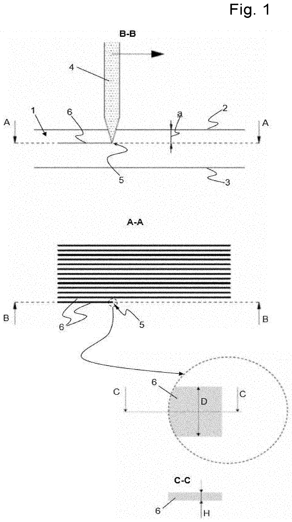
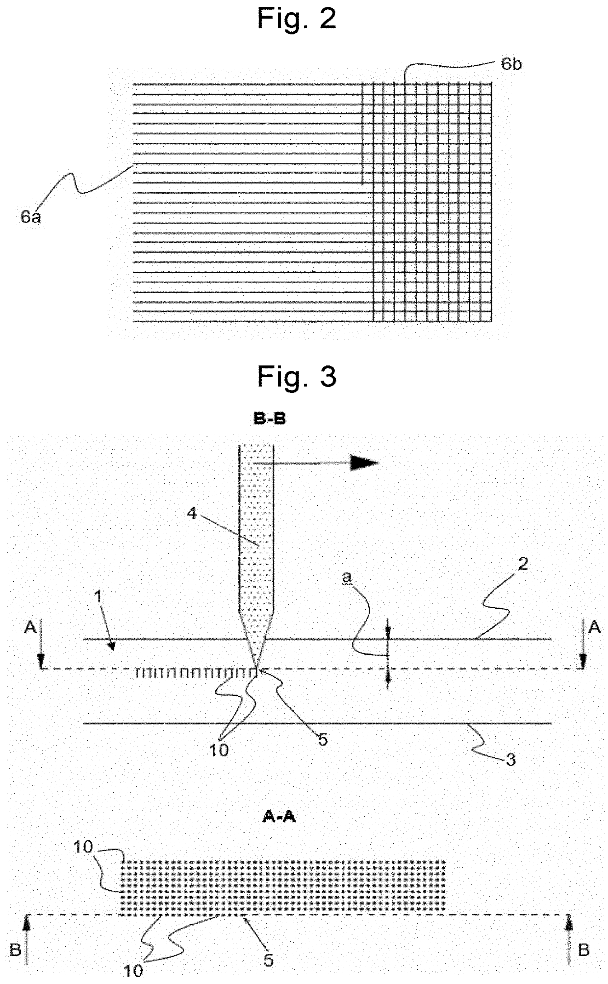
[0011]In both modes of operation of the invention, respectively illustrated in FIGS. 1 and 3, a transparent sapphire watch crystal 1 is marked by a laser beam 4 oriented perpendicularly to upper surface 2 and focused on a point 5 inside the crystal.

[0012]In the non-limiting examples represented, crystal 1 has an upper surface 2 and a lower surface 3, which are essentially plane and parallel with respect to one another. According to the first mode of operation (FIG. 1), beam 4 is scanned over part of the surface of crystal 1, following a number of juxtaposed linear paths, thus producing a hatched marking. The distance ‘a’ between the laser focal point 5 and upper surface 2 remains essentially fixed during the scanning phase. The parameters applied for hatching are such that each scan along a linear path will produce an opaque area 6 inside the sapphire, the area being essentially rectilinear and perpendicular to the direction of the beam (or parallel to the upper surface of the cryst...


PUM

PropertyMeasurementUnit
Fractionaaaaaaaaaa
Speedaaaaaaaaaa
Speedaaaaaaaaaa

Abstract

A method for marking a sapphire watch crystal, through the interaction between a laser beam and the sapphire. The beam is focused on a point inside the crystal and the interaction is such that it produces a rectilinear opaque area, which is parallel to the upper surface of the crystal or perpendicular to the surface. The orientation of the opaque area depends on the mode of operation applied. According to the hatching mode of operation, the beam is scanned along one or more linear paths, producing opaque lines inside the crystal, which are parallel to the upper surface. The perforation mode of operation produces distinct opaque areas, obtained by discontinuous operation of the beam on a number of juxtaposed points. According to this latter mode of operation, the opaque areas extend in the direction perpendicular to the upper surface of the crystal.

Description

FIELD OF THE INVENTION[0001]The present invention relates to horology, in particular to the marking of a watch crystal, to add to the crystal a serial number, picture or logo, or any other type of information and / or aesthetic mark. The invention is more particularly focused on the marking of a sapphire watch crystal.STATE OF THE ART[0002]A known technique for obtaining a marking consists in etching the crystal using a laser. On sapphire crystals, it is known to use a laser that is focused on the upper surface of the crystal and to scan the laser over part of the surface, in order to remove material, thereby creating a break in the crystal lattice and making the material opaque. The material removed must be evacuated in the form of dust, which represents a drawback of this approach, since dust is likely to contaminate the marking.[0003]Another technique for marking watch crystals made of sapphire or other materials consists in etching the material with a laser focused inside the crys...

Claims


Application Information

Patent Timeline
IPC IPC(8): G04B39/00B23K26/362B23K26/402
CPCG04B39/006B23K26/402B23K26/362B23K26/50G04B45/0084B41M5/262B23K26/53B23K26/032B23K26/359B23K26/364
Inventor NETUSCHILL, ALEXANDRE
Owner COMADUR
Why Eureka
Eureka Blog
Learn More