Linked Locking Mechanism and Antenna Down-tilt Angle Control Device

a locking mechanism and control device technology, applied in the direction of antenna supports/mountings, mechanical devices, antennas, etc., can solve the problems of insufficient positioning function and complicated transmission structure of traditional electronic down-tilt, and achieve independent and accurate control of the down-tilt angle, easy to locate

Active Publication Date: 2020-09-24
COMBA TELECOM TECH (GUANGZHOU) CO LTD
View PDF0 Cites 3 Cited by
  • Summary
  • Abstract
  • Description
  • Claims
  • Application Information

AI Technical Summary

Benefits of technology

[0004]Based on this, it is necessary to provide a linked locking mechanism and antenna down-tilt angle control device.

Problems solved by technology

The structure of transmission of a traditional electronic down-t

Method used


Image

  • Linked Locking Mechanism and Antenna Down-tilt Angle Control Device
  • Linked Locking Mechanism and Antenna Down-tilt Angle Control Device
  • Linked Locking Mechanism and Antenna Down-tilt Angle Control Device

Examples


Embodiment Construction

[0090]To make the objectives, technical solution, and advantages of the present invention clearer, the following further describes the present invention in detail with reference to the accompanying drawings and specific embodiments. It should be understood that the specific embodiments described herein are only used to explain the present invention, and do not limit the protection scope of the present invention.

[0091]It should be noted that when an element is called “fixed to” another element, it can be directly located on another element or there can be an intermediate element. At the same time, fixing method of the two can be detachable and fixed, or can be a non-detachable connection. Specifically, it can be such as sleeve connection, snap connection, integral molding or welding. When an element is considered to be “connected” to another element, it can be directly connected to the other element or an intermediate element may also be present. When one component is considered as a...


PUM


Abstract

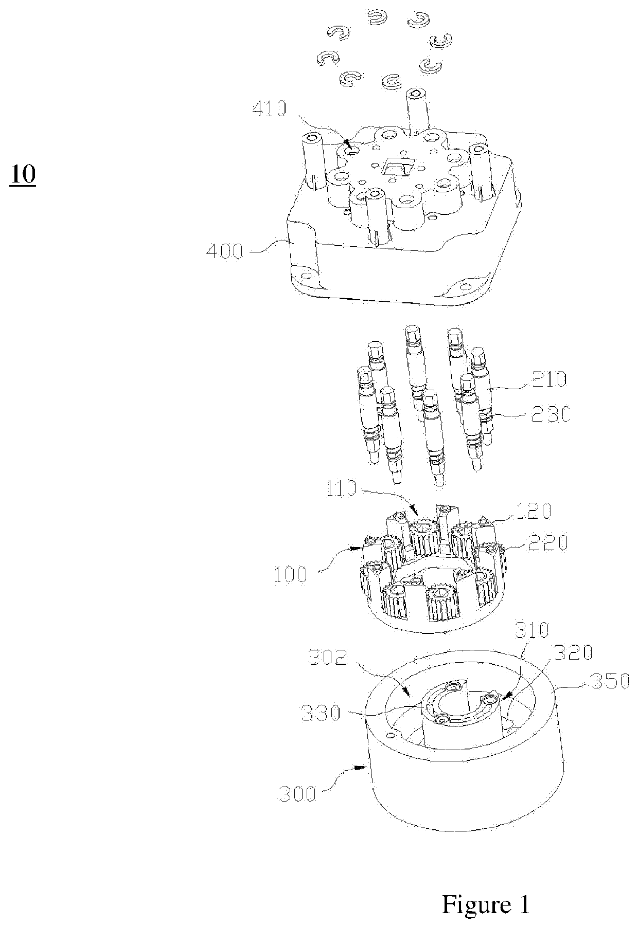
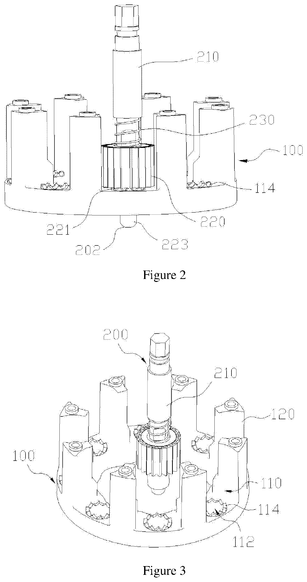
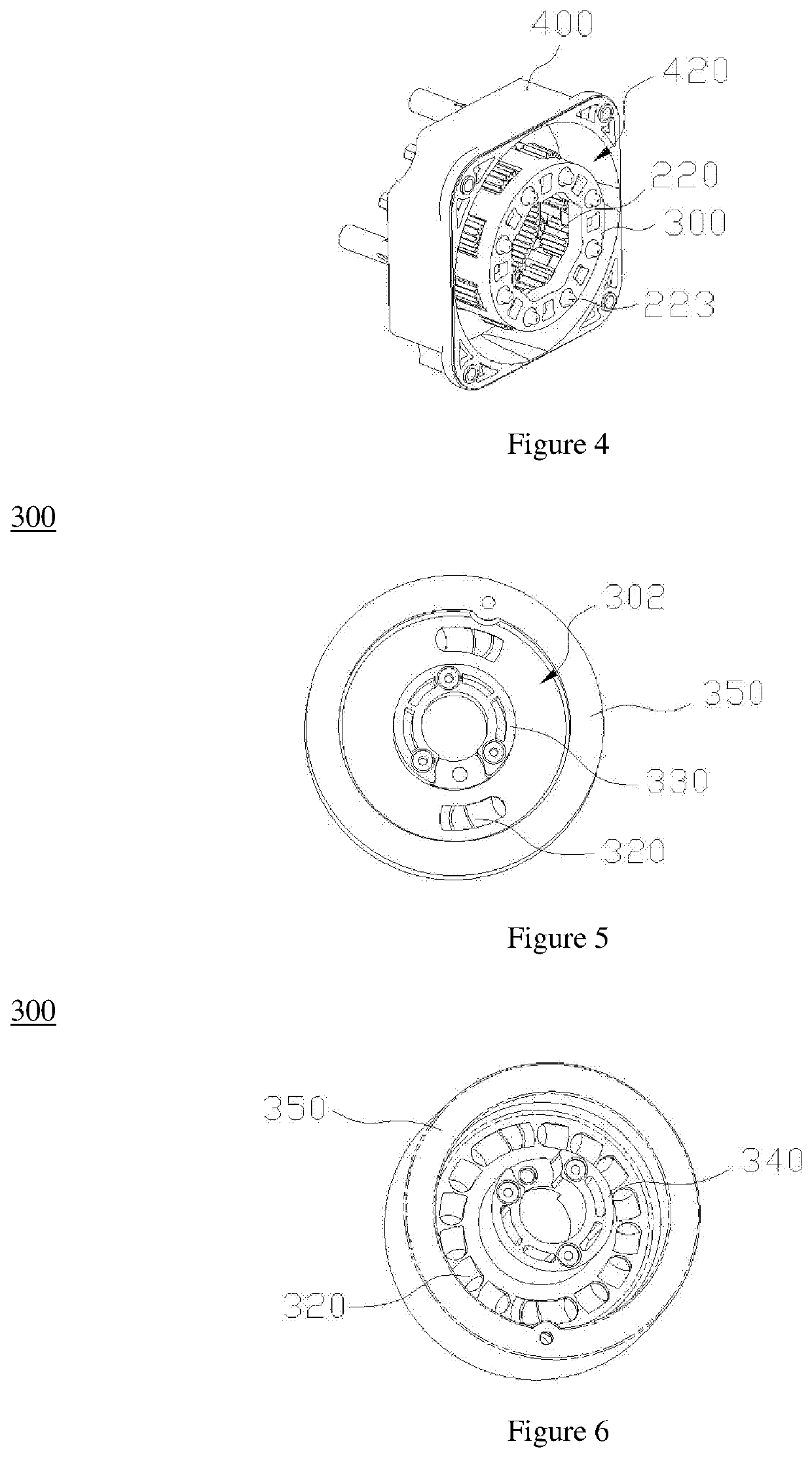
A linked locking mechanism and antenna down-tilt angle control device is described. Linked locking mechanism includes: mounting frame with a mounting positions, each mounting position has a mounting through hole and a clamping body. Output assembly includes an output shaft and output gear resiliently disposed on output shaft. One end of output gear has engaging body engaged with clamping body and pressing body provided through mounting through hole. Rotating bracket has pressure bearing surface pressed against pressing body. Arc-shaped embossments are provided on pressure bearing surface. The arc-shaped embossment includes guide end, anti-reverse end, and mating body. When mating body and pressing body abut, and engaging body and clamping body are separated, output gear drives output shaft to rotate. Linked locking mechanism and antenna down-tilt angle control device provide easy positioning and accurate control of down-tilt angle of antenna.

Description

FIELD OF THE INVENTION[0001]The present invention relates to the technical field of mobile communication devices, and in particular, to a linked locking mechanism and antenna down-tilt angle control device.BACKGROUND OF THE INVENTION[0002]As the number of mobile communication terminal users continues to increase, the network capacity requirements of sites in a mobile cellular network are increasing, and at the same time, the interference between different sites or even between different sectors of the same site is required to be minimized, that is to maximize network capacity and minimize interference. To achieve this object, an antenna beam down-tilt on a drive station is usually used.[0003]At present, the method of driving a beam down-tilt includes: mechanical down-tilt and electronic down-tilt, and electronic down-tilt has obvious advantages, which is the current mainstream and future development trend. The structure of transmission of a traditional electronic down-tilt is compli...

Claims


Application Information

Patent Timeline
IPC IPC(8): H01Q3/04H01Q1/12F16H3/08
CPCF16H3/08H01Q1/125H01Q3/04F16H3/60F16H3/70F16H2035/005H01Q3/06H01Q1/246
Inventor HUANG, CHAOSHENGMA, ZEFENGXUE, FENGZHANGYOU, JIANJUNDUAN, HONGBINLIU, PEITAO
Owner COMBA TELECOM TECH (GUANGZHOU) CO LTD
Why Eureka
Try Eureka