Supercharge Your Innovation With Domain-Expert AI Agents!

Sepsis detection and monitoring

a technology for sepsis and detection and monitoring, applied in the field of sepsis detection and monitoring, can solve the problems of difficult to distinguish sepsis from other diseases, increase the risk of dying, and life-threatening sepsis, and achieve the effect of maximizing the strength of optical signals

Pending Publication Date: 2020-10-01
WELCH ALLYN INC
View PDF5 Cites 3 Cited by
  • Summary
  • Abstract
  • Description
  • Claims
  • Application Information

AI Technical Summary

Benefits of technology

The sensor device described in this patent has a special optical block that prevents direct light signals from being transmitted from the emitter to the detector without being reflected back from a blood vessel. A second polarizer filters the reflected signals to only receive the ones that reflect off a blood vessel. The orientation of the first and second polarizers can be adjusted to align with the orientation of a blood vessel to maximize the strength of the reflected signals from the blood vessel. The angles of incidence of the first and second polarizers are modulated based on the induced temperature change. Overall, this design ensures accurate and reliable detection of blood vessels.

Problems solved by technology

Sepsis is a life-threatening condition that occurs when the body's response to infection causes injury to its own tissues and organs.
In early stages, it is difficult to differentiate sepsis from other diseases because certain symptoms of sepsis, such as fever, increased heart rate, and breathing rate, mimic the symptoms of other diseases.
However, as time progresses the risk of dying increases substantially.
The costs of enrolling a non-septic patient include unnecessary hospital admission, antibiotics, blood draws, and blood cultures, and failure to address the patient's actual clinical need.
The costs of a false negative include, at worst, patient death and, at best, longer length of stay at a higher acuity ward such as an ICU.
The combination of the high mortality rate of sepsis and the difficulty differentiating it from other diseases leads to current systems for sepsis detection to be biased toward false positives.

Method used


Image

  • Sepsis detection and monitoring
  • Sepsis detection and monitoring
  • Sepsis detection and monitoring

Examples


Embodiment Construction

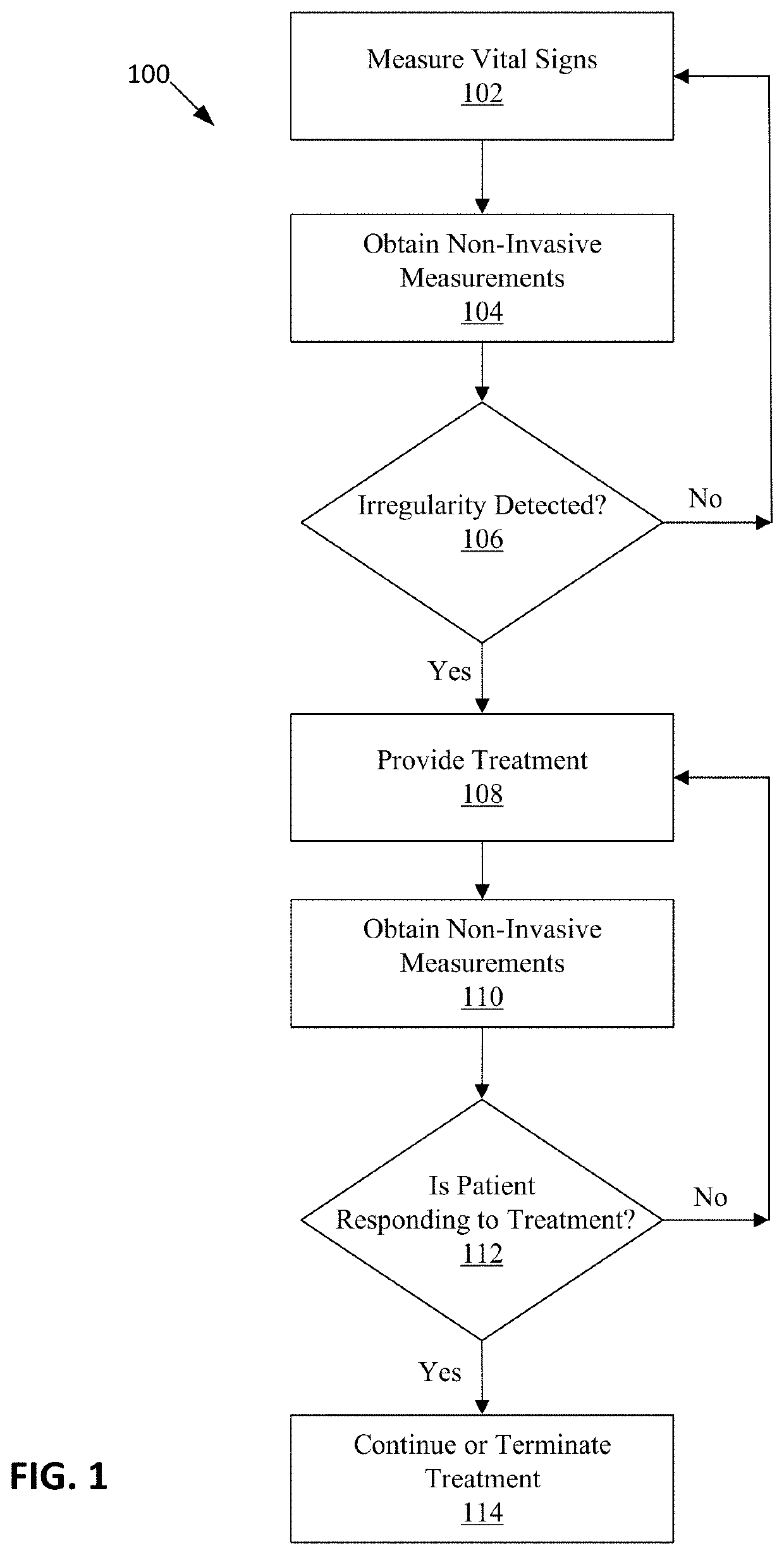
[0045]FIG. 1 illustrates a method 100 of detecting and monitoring sepsis. The method 100 includes measuring vital signs (Step 102); obtaining non-invasive measurements (Step 104); determining if an irregularity is detected (Step 106); providing treatment (Step 108); obtaining additional non-invasive measurements during treatment (Step 110); determining whether a septic patient is responding to treatment (Step 112); and continuing or terminating treatment (Step 114).

[0046]Referring now to Step 102, vital sign measurements are obtained from a vital signs monitor such as a Connex® spot monitor available from Welch Allyn Inc., Skaneateles Falls, N.Y. In one example embodiment, heart rate variability is measured in Step 102 because heart rate variability has been shown to decrease before the clinical onset of sepsis. Heart rate variability is a measure of the variation in time between each heartbeat. If a decrease in heart rate variability is detected, the rate of acquiring the vital sig...


PUM


Abstract

A sensor device includes a housing defining a cavity, an inlet to receive fluid pumped from an instrument device, an outlet to return the fluid to a fluid reservoir, and a fluid channel defined inside the cavity between the inlet and the outlet. A heat pump is mounted inside the cavity, and has a side surface thermally coupled to the fluid channel and an opposite side surface thermally coupled to a plate. The heat pump is configured to induce a temperature change. A sensor unit is aligned with an aperture in the plate and includes an optical component and a thermal component. The optical component configured to measure a vascular endothelial response from the induced temperature change.

Description

INTRODUCTION[0001]Sepsis is a life-threatening condition that occurs when the body's response to infection causes injury to its own tissues and organs. Sepsis develops when a pathogen is released into the bloodstream and causes inflammation throughout the entire body.[0002]In early stages, it is difficult to differentiate sepsis from other diseases because certain symptoms of sepsis, such as fever, increased heart rate, and breathing rate, mimic the symptoms of other diseases. The ability to detect sepsis at its earliest stages is critical because early sepsis is usually reversible with antibiotics, fluids, and other supportive medical interventions. However, as time progresses the risk of dying increases substantially.[0003]The costs of enrolling a non-septic patient include unnecessary hospital admission, antibiotics, blood draws, and blood cultures, and failure to address the patient's actual clinical need. The costs of a false negative include, at worst, patient death and, at be...

Claims


Application Information

Patent Timeline
IPC IPC(8): A61B5/00A61B5/1455A61B5/1491
CPCA61B5/14552A61B5/412A61B5/1491A61B5/742A61B5/6831A61B5/14558A61B5/0048A61B5/02007A61B3/12A61B5/0531A61B3/0025
Inventor BAKER, STEVEN D.CHAHAL, JOTPREETFITZGIBBONS, STACEYMEYERSON, CRAIG .MQUINN, DAVID E.ZAPFE, LORI ANNWOLFE, GENE J.
Owner WELCH ALLYN INC
Features
  • R&D
  • Intellectual Property
  • Life Sciences
  • Materials
  • Tech Scout
  • Unparalleled Data Quality
  • Higher Quality Content
  • 60% Fewer Hallucinations
Learn More