Drive unit for a slide-out room

a technology for driving units and slide-out rooms, which is applied in the direction of mechanical equipment, vehicles with living accommodation, belts/chains/gearrings, etc., can solve the problems of reducing limiting the amplitude of movement of the slide-out, and time-consuming and difficult installation of existing retractable or slide-out rooms, etc., to achieve better control of operation and reduce the load of each drive uni

Active Publication Date: 2020-10-01
LCI ITAL SRL
View PDF0 Cites 0 Cited by
  • Summary
  • Abstract
  • Description
  • Claims
  • Application Information

AI Technical Summary

Benefits of technology

[0009]Therefore, a need exists for an improved drive mechanism for a slide-out room of a recreation-al vehicle. It is an object of this invention to provide a drive unit for a slide-out room of a recreational vehicle for realizing such an improved drive mechanism which also provides for an excellent water seal.

Problems solved by technology

Existing retractable or slide-out rooms can be time-consuming and difficult to install.
A problem with this type of mechanism is that the length of a drive screw limits the amplitude of movement of the slide-out room because the amplitude cannot be greater than the length of the drive-screw.
Screws, however, should be short for practical reasons, including the tendency of a longer screw to deflect so that the axis of the screw is no longer absolutely straight, which greatly impairs operability of the screw.
A problem with this type of mechanism is that the geared racks arranged on the exterior surfaces of the slide-out room are usually exposed to the environment when the slide-out room is extended and may thus attract or otherwise engage with dirt, debris, or foreign objects that could hinder proper operation of the mechanism and allow for moisture to enter the vehicle.
These mechanisms employing cables are usually complicated to install and to maintain and are often prone to failure.

Method used


Image

  • Drive unit for a slide-out room
  • Drive unit for a slide-out room
  • Drive unit for a slide-out room

Examples


Embodiment Construction

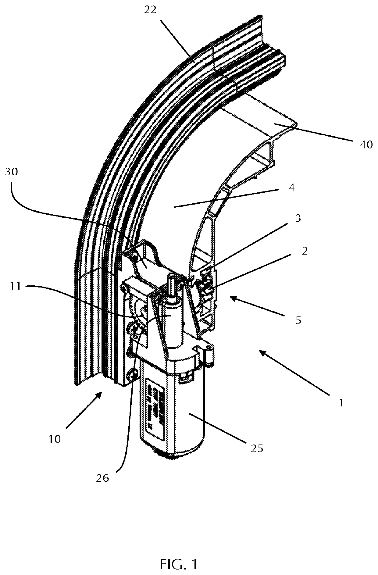
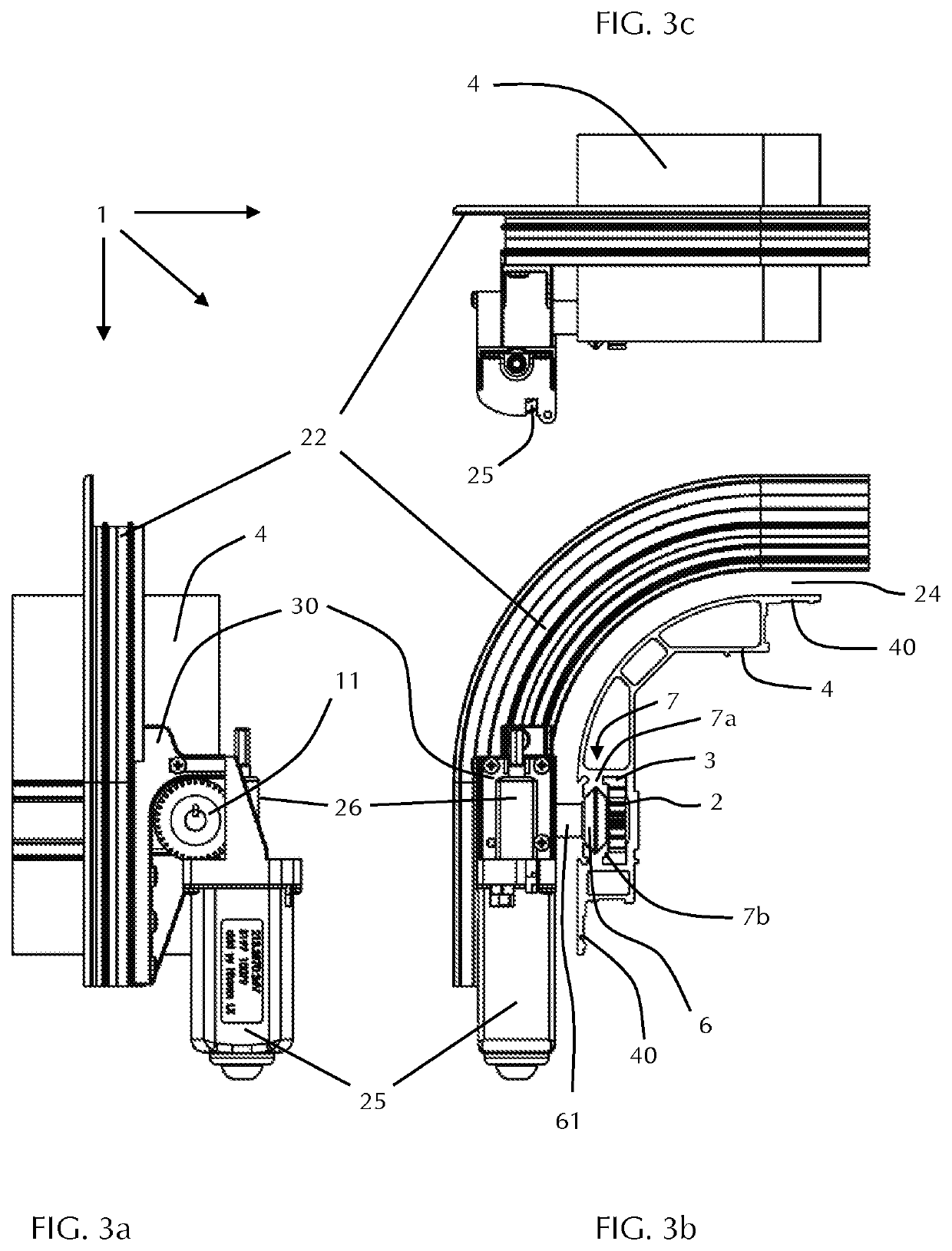
[0057]FIG. 1 shows a perspective view of a drive unit 1 in accordance with the invention. The drive unit 1 comprises a rotary component 2, an elongate component 3, and a structural member 4. In the embodiment shown in FIG. 1 the rotary component 2 is a pinion and the elongate component 3 is a rack. Pinion 2 meshes with rack 3 such that a rotary motion of pinion 2 results in a linear motion of rack 3. Rack 3 is connected to or integrated into structural member 4 in such a way that rack 3 will take along structural member 4 as rack 3 is being driven by pinion 2.

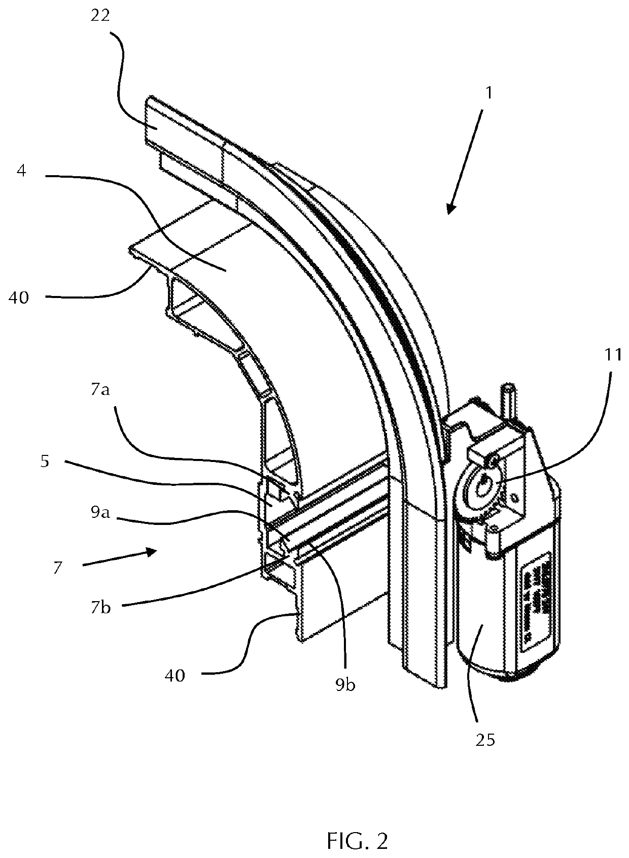
[0058]As shown in FIG. 1, structural member 4 comprises an elongate cavity 5, and pinion 2 and rack 3 are arranged within this elongate cavity 5. Furthermore, structural member 4 is configured to be coupled to a wall panel of a slide-out room. To this end, structural member 4 comprises mounting portions for mounting wall panels to the structural member. In the embodiment shown in FIG. 1 these mounting portions are implemented b...


PUM


Abstract

A drive unit for a slide-out room of a recreational vehicle includes a rotary component, an elongate component, and a structural member configured to be coupled to a wall panel of the slide-out room and having an elongate cavity. The elongate component and the rotary component are arranged within the elongate cavity of the structural member and are configured to mesh such that a rotary motion of the rotary component results in a linear motion of the elongate component together with the structural member relative to the rotary component. Advantageously, the drive unit may further include a guide member and a guide rail, where the guide rail is integrated into the elongate cavity of the structural member and where the guide member and the guide rail are configured to cooperate to support the linear motion of the structural member.

Description

CROSS-REFERENCES TO RELATED APPLICATIONS[0001]This application claims the benefit of European Patent Application No. 19165211.4, filed Mar. 26, 2019, the entire content of which is herein incorporated by reference.STATEMENT REGARDING FEDERALLY SPONSORED RESEARCH OR DEVELOPMENT[0002](Not applicable)BACKGROUND[0003]This invention relates to a drive unit for a slide-out room, more specifically to a drive unit for a slide-out room of a recreational vehicle or similar mobile living quarters. The invention furthermore relates to a slide-out room assembly comprising such a drive unit.[0004]It is generally known to provide recreational vehicles, such as motor homes, fifth-wheel trailers, and travel trailers with a retractable or slide-out room for increasing the living space of the vehicle. The retractable or slide-out room may be extended for use when the vehicle is parked and should be retracted into the main living area of the vehicle when the vehicle is to be moved. In other words, a sl...

Claims


Application Information

Patent Timeline
Patent Type & Authority Applications(United States)
IPC IPC(8): B60P3/34F16H25/20
CPCB60P3/34F16H25/20
Inventor REVELINO, LAWRENCEWILKINS, RUPERTROMAGNOLI, FABIORODABAUGH, DANIEL K.
Owner LCI ITAL SRL
Why Eureka
Try Eureka