Lighting device with transparent stabilizer element

a technology of stabilizer element and light source, which is applied in the direction of refractors, light and heating equipment, transportation and packaging, etc., can solve the problems of thermal stress inside the lighting device, deformation of light guides, and displaced light sources, so as to reduce the thermal sensitivity of the lighting device, simple and cost-effective

Active Publication Date: 2020-10-01
LUMILEDS
View PDF0 Cites 4 Cited by
  • Summary
  • Abstract
  • Description
  • Claims
  • Application Information

AI Technical Summary

Benefits of technology

[0009]It is an object of the present invention to provide a lighting device comprising multiple light-emitting elements and light guides, wherein the thermal sensitivity of the lighting device is reduced in a particularly simple manner. It is also an object of the invention to provide a cost-effective method for producing such a lighting device.

Problems solved by technology

A challenge when using light-emitting elements, such as LEDs, for purposes requiring high intensities such as automotive headlights is the high heat load that is generated when operating the lighting device.
The heat load leads to thermal stresses inside the lighting device, such that light guides may deform and may be displaced relative to the light-emitting elements.
This effect may become significant when an arrangement of relatively close-packed light-emitting elements is used, leading to an uneven thermal expansion of the finger-shaped collimator.
Moreover, as the heat load is higher in the center than near the edges of the arrangement of light-emitting elements, a bulging effect of the finger-shaped collimator may occur, which misaligns the light guides relative to the light-emitting elements by tilting the fingers of the collimator.

Method used


Image

  • Lighting device with transparent stabilizer element
  • Lighting device with transparent stabilizer element
  • Lighting device with transparent stabilizer element

Examples


Embodiment Construction

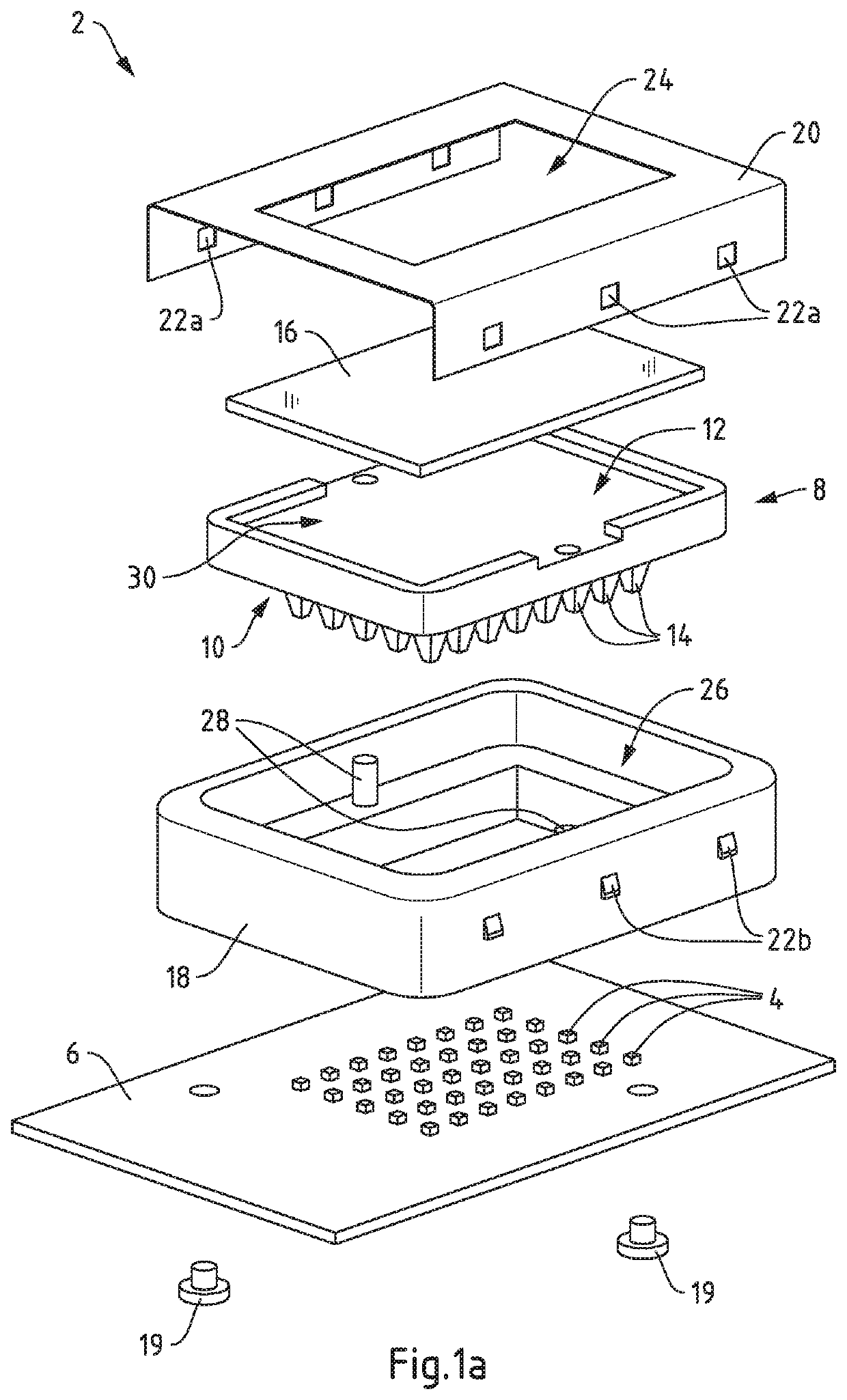
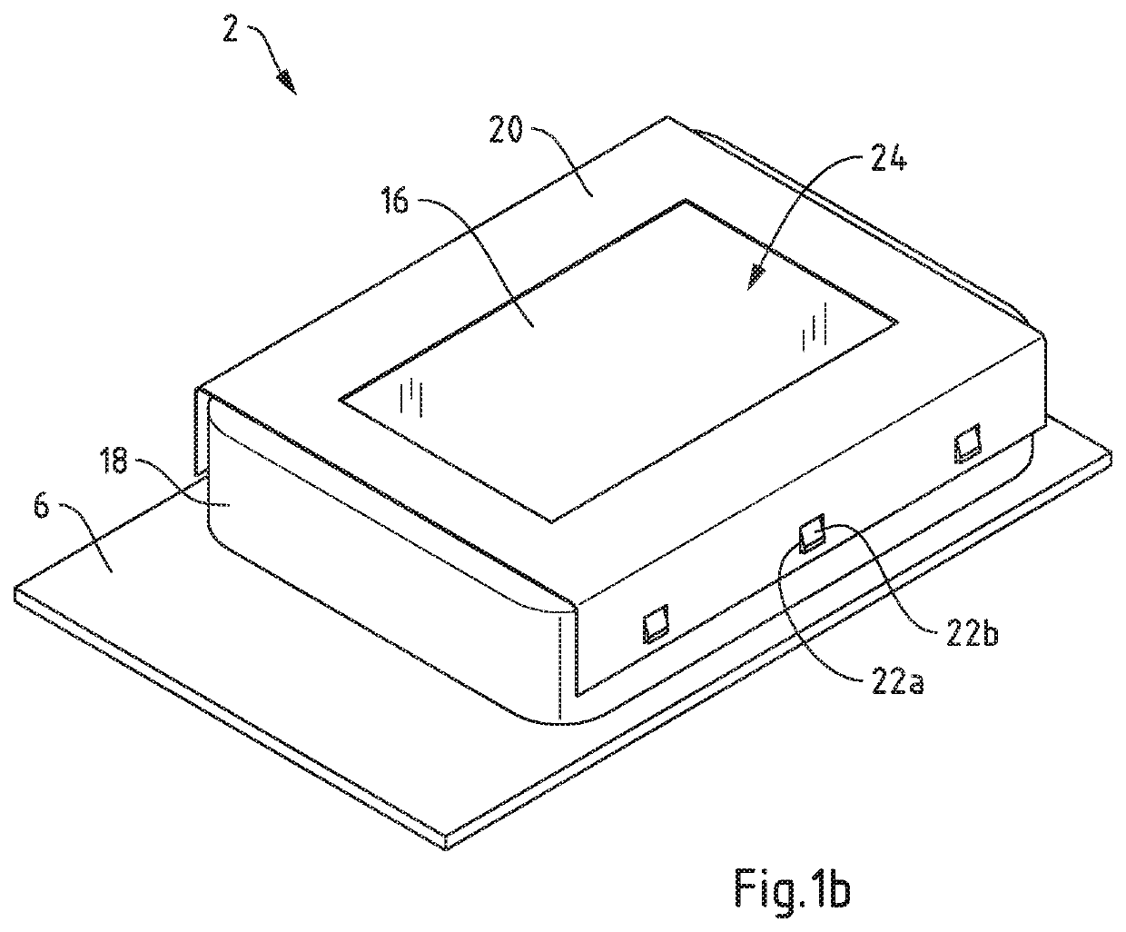
[0049]FIG. 1a schematically shows a lighting device 2 according to the invention in an exploded view. Correspondingly, FIG. 1b schematically shows the embodiment of the lighting device 2 according to the invention in a perspective view. The lighting device 2 comprises light-emitting elements 4 arranged on a substrate 6, which is configured as a printed circuit board. The light-emitting elements 4 are arranged in a 5×6 matrix on the substrate 6.

[0050]A lens 8 with a light entry side 10 and a light exit side 12 is provided, the lens 8 being configured as an integral element with an array of light guides 14. Each light guide 14 is configured for an optical contact to one of the light-emitting elements 4, wherein the light guides 14 form a matrix corresponding to the matrix of light-emitting elements 4. The light guides 14 are configured to guide light emitted by the corresponding light-emitting element 4, to which an optical contact is made, towards the light entry side 10 of the lens ...


PUM

PropertyMeasurementUnit
transparentaaaaaaaaaa
thermal stressesaaaaaaaaaa
thermal expansionaaaaaaaaaa

Abstract

The present disclosure relates to a lighting device comprising light-emitting elements such as light-emitting diodes arranged on a substrate. The object to provide a lighting device comprising multiple light-emitting elements and light guides, wherein the thermal sensitivity of the lighting device is reduced in a particularly simple manner, is solved in that the lighting device comprises: a lens with a light entry side and a light exit side; light guides, each light guide being arranged in optical contact to at least one of the light-emitting elements and being configured to guide light emitted by the at least one of the light-emitting elements towards the light entry side of the lens; and a transparent stabilizer element being arranged in mechanical contact to the light exit side of the lens, wherein the transparent stabilizer element is configured to define the shape of the light exit side of the lens at least in regions. The invention further refers to a method for producing a lighting device.

Description

CROSS REFERENCE TO RELATED APPLICATIONS[0001]This application claims priority to European Patent Application No. 19165183.5 filed on Mar. 26, 2019, and European Patent Application No. 19186927.0 filed on Jul. 18, 2019, both of which are incorporated herein by reference.FIELD OF THE INVENTION[0002]The present disclosure relates to a lighting device, comprising multiple light-emitting elements such as light-emitting diodes (LEDs) arranged on a substrate and light guides guiding light from the light-emitting elements towards a lens, in particular in the field of automotive lighting.BACKGROUND OF THE INVENTION[0003]Lighting devices comprising multiple light-emitting elements are used to provide a higher light output, and may further allow for a variation in beam shape and emitted intensity. For instance, adaptive headlights in automobiles may comprise a matrix arrangement of light-emitting elements, wherein sections of light-emitting elements may be addressed independently of each other...

Claims


Application Information

Patent Timeline
Patent Type & Authority Applications(United States)
IPC IPC(8): F21S45/47F21S41/24F21V5/00F21S41/143F21S41/153F21S41/20
CPCF21S41/24F21V5/008F21S41/153F21S41/143F21S45/47F21S41/285F21S41/19F21S41/29F21S41/322
Inventor MONESTIER, FLORENTSPINGER, BENNOHECHTFISCHER, ULRICH
Owner LUMILEDS
Why Eureka
Try Eureka