Lens configuration for a thermally compensated chromatic confocal point sensor

a confocal point sensor and lens configuration technology, applied in the field of precision measurement instruments, can solve problems such as the introduction of surface height measurement errors, and achieve the effects of reducing the complexity and overall expense of the lens configuration, reducing thermal sensitivity, and reducing the spot size, measurement range and stando

Active Publication Date: 2011-09-22
MITUTOYO CORP
View PDF25 Cites 4 Cited by
  • Summary
  • Abstract
  • Description
  • Claims
  • Application Information

AI Technical Summary

Benefits of technology

[0016]In accordance with another aspect of the invention, in one embodiment, each lens element of the chromatically dispersive lens configuration has spherical surfaces. The utilization of spherical lenses reduces the complexity and overall expense of the lens configuration.
[0017]A chromatic confocal point sensor optical pen using a chromatically dispersive lens configuration including thermal compensation according to this invention has the advantage of a decreased thermal sensitivity while maintaining a desirable optical throughput, spot size, measurement range and standoff, while using a relatively simple lens configuration. Previously, such simple optical pen lens configurations (e.g., as disclosed in the '705 patent) were associated with significantly higher thermal sensitivities. For example, in one embodiment, an optical pen according to the '705 patent may have a thermal sensitivity on the order of 210 nm / ° C., whereas an optical pen using a chromatically dispersive lens configuration including thermal compensation according to this invention may have a thermal sensitivity of on the order of 70 nm / ° C. using similar housing materials, or less if other materials and design features are also modified.

Problems solved by technology

This thermal sensitivity changes the Z height where a given wavelength is best focused, and therefore introduces errors in surface height measurements.

Method used


Image

  • Lens configuration for a thermally compensated chromatic confocal point sensor
  • Lens configuration for a thermally compensated chromatic confocal point sensor
  • Lens configuration for a thermally compensated chromatic confocal point sensor

Examples


Embodiment Construction

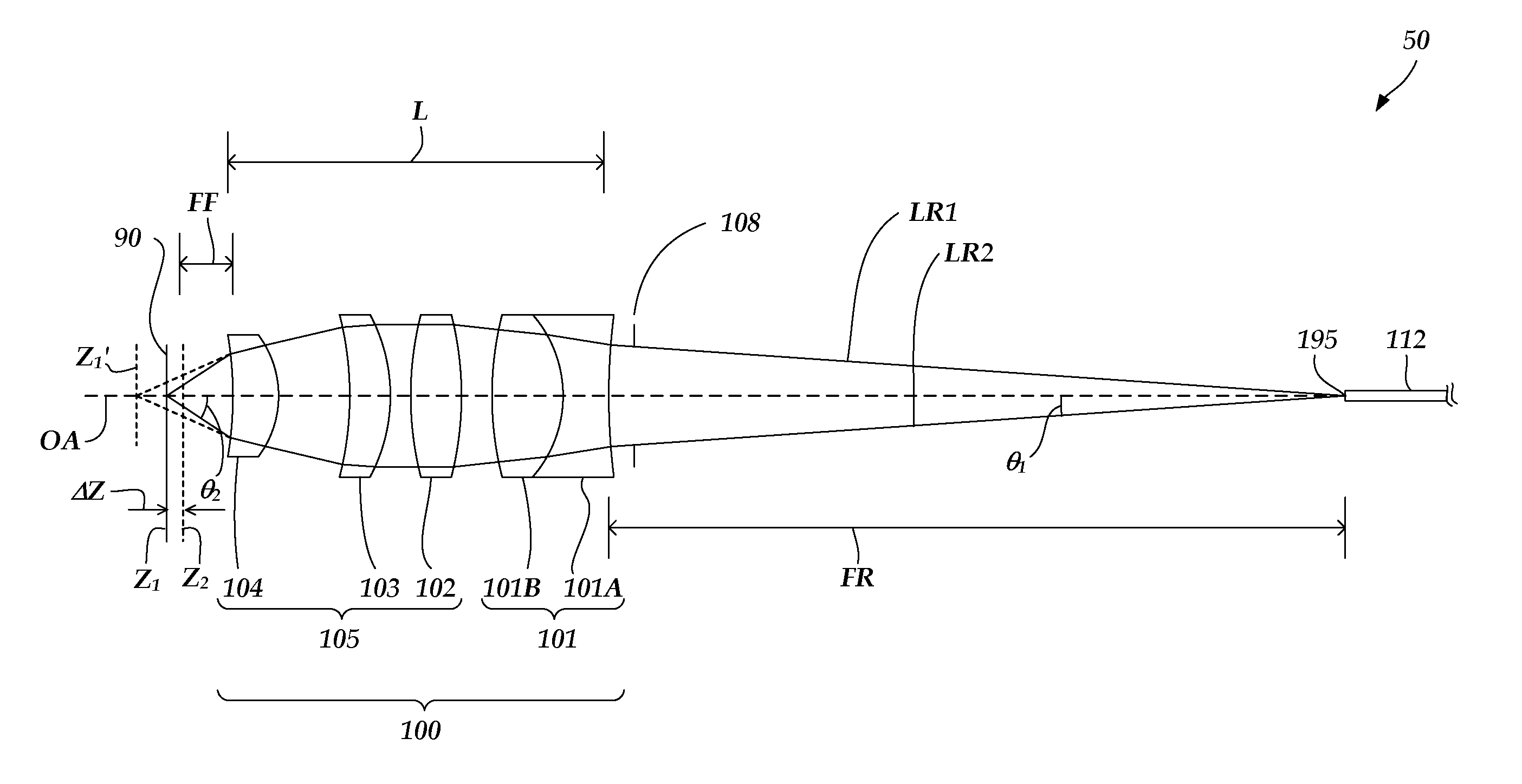
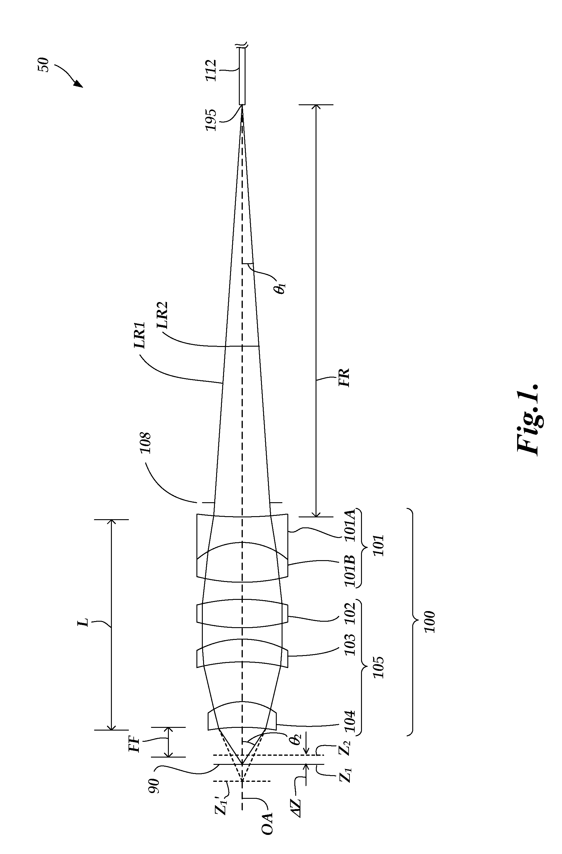
[0023]FIG. 1 is a diagram 50 of a schematic side view of the operation of an exemplary embodiment of a chromatically dispersive lens configuration 100, according to this invention. The lens configuration 100 includes a doublet lens element 101, and a positive power lens portion 105. It will be appreciated that the lens configuration 100 is exemplary only, and not limiting. In various embodiments, the positive power lens portion comprises at least two lens elements. In some embodiments, the positive power lens portion comprises at most four lens elements. In the specific embodiment shown in FIG. 1, the positive power lens portion 105 includes a bi-convex lens element 102, and meniscus lens elements 103 and 104. The doublet lens element 101 is formed from a first lens portion 101A and second lens portion 101B. The meniscus lens elements 103 and 104 have both surfaces curved in the same direction, and are oriented so as to provide positive optical power and focus the radiation output f...


PUM


Abstract

A chromatically dispersive lens configuration including thermal compensation may be utilized in chromatic confocal point sensor optical pens for chromatic range sensing. The lens configuration may include a negative power doublet lens and a positive power lens portion. The positive power lens portion comprises at least two lens elements which compensate for the overall thermal sensitivity of a chromatic confocal point sensor optical pen. The lens elements of the positive power lens portion which compensate for thermal sensitivity have an average coefficient of thermal defocus which is in a range that is at lowest 10 ppm per 10° C. The lens configuration can be implemented with dimensions which fit a standard commercial chromatic confocal point sensor optical pen, while maintaining a level of optical performance sufficient for chromatic range sensing.

Description

FIELD OF THE INVENTION[0001]The invention relates generally to precision measurement instruments, and more particularly to a chromatic sensor lens configuration such as may be utilized in an optical pen for chromatic confocal range sensing.BACKGROUND OF THE INVENTION[0002]Controlled chromatic aberration techniques may be utilized for distance sensing metrology applications. As described in “Pseudocolor Effects of Longitudinal Chromatic Aberration,” G. Molesini and S. Quercioli, J. Optics (Paris), 1986, Volume 17, No. 6, pages 279-282, controlled longitudinal chromatic aberration may be introduced in an optical imaging system, causing the imaging system focal length to vary with wavelength, which provides means for optical metrology. In particular, a lens can be designed whose back focal length (BFL) is a monotonic function of wavelength. In white light operation such a lens exhibits a rainbow of axially dispersed foci that can be used as a spectral probe for distance sensing applica...

Claims


Application Information

Patent Timeline
Patent Type & Authority Applications(United States)
IPC IPC(8): G01C3/08
CPCG01B11/026G01B11/24G02B27/20G02B7/028G02B13/14G01B2210/50
Inventor XIE, YONGBAQUI, BERNADETTE T.JONES, BENJAMIN K.
Owner MITUTOYO CORP
Why Eureka
Try Eureka