
Electronic device

a technology of electronic devices and wing accessories, which is applied in the direction of instruments, details of portable computers, wing accessories, etc., can solve the problems of reducing the performance of notebook computers and the inability of wide side frames to visually conform to design trends, so as to enhance the performance of function assemblies and/or heat dissipation openings

Active Publication Date: 2020-10-01
COMPAL ELECTRONICS INC
View PDF0 Cites 3 Cited by
  • Summary
  • Abstract
  • Description
  • Claims
  • Application Information

AI Technical Summary

Benefits of technology

The disclosure is about an electronic device with a hinge assembly that allows for good performance and slim side frames. The hinge assembly includes a connection portion that shifts relative to the device's casing when the hinge assembly rotates, exposing the function assembly and heat dissipation opening at the end. This improves the function assembly and heat dissipation opening's performance. The design also satisfies the trend of slim side frames by gradually increasing the region of the side frame covered by the device's casing during operation.

Problems solved by technology

However, due to the limitation of configuration space, the function assemblies and heat dissipation openings are often covered by the casings of the notebook computer, which reduces the performance of the notebook computer.
However, the wide side frame cannot visually comply with the design trend of slim side frames of the existing electronic devices.

Method used


Image

  • Electronic device
  • Electronic device
  • Electronic device

Examples


Embodiment Construction

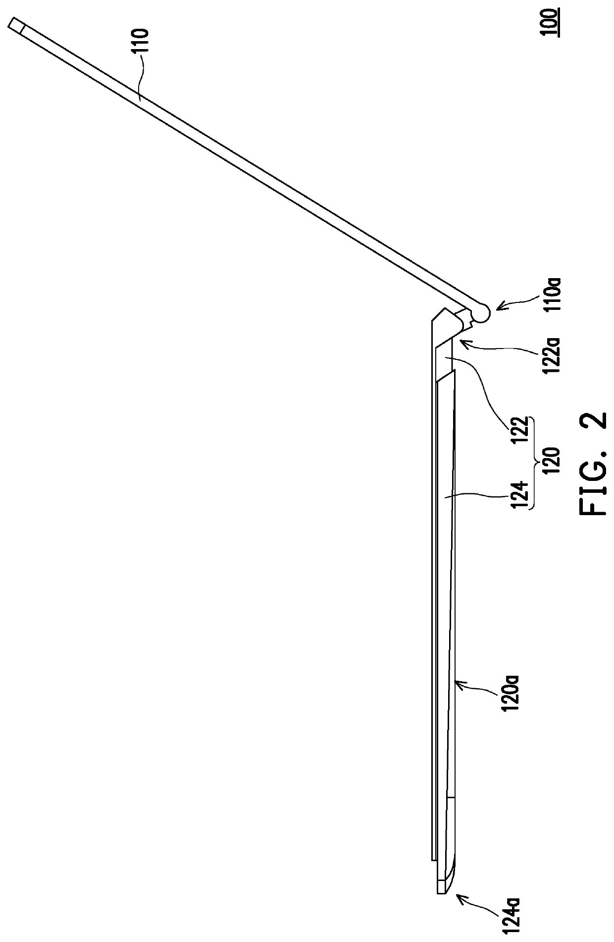
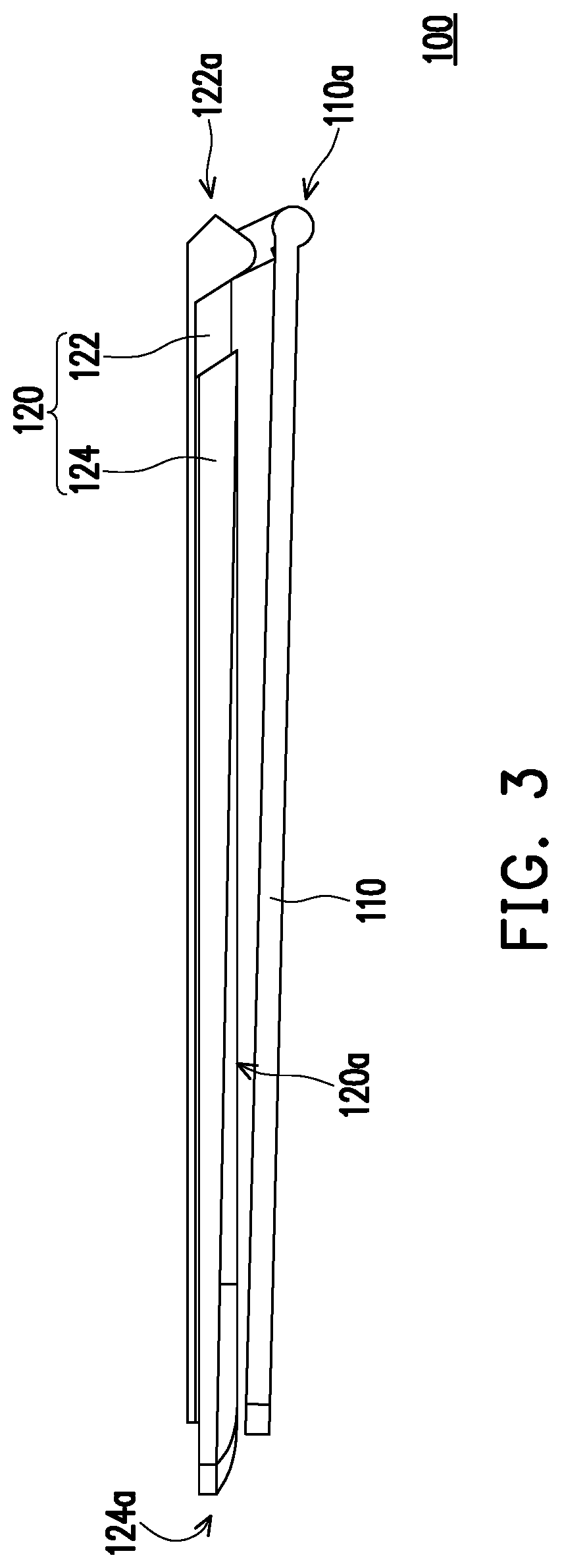
[0039]FIG. 1 is a side view illustrating an electronic device according to an embodiment of the disclosure. FIG. 2 illustrates that the first body depicted in FIG. 1 is unfolded relative to the second body. FIG. 3 illustrates that the first body depicted in FIG. 2 flips to the back surface of the second body. With reference to FIG. 1 to FIG. 3, an electronic device 100 provided in the embodiment is, for instance, a notebook computer and includes a first body 110 and a second body 120. The first body 110 is, for instance, a display of the notebook computer, and the second body 120 is, for instance, a host of the notebook computer. The first body 110 may be folded to the second body 120 as shown in FIG. 1, so that the electronic device may be easily stored or carried. The first body 110 may be unfolded relative to the second body 120 as shown in FIG. 2, so that a user may easily operate the second body 120 and view a display image of the first body 110. In addition, the first body 110...


PUM


Abstract

An electronic device includes a first body, a second body, a hinge assembly, and a linkage assembly. The first body has a first pivoting end. The second body includes first and second casings slidably disposed on each other. The first casing has a second pivoting end. The hinge assembly has a first axial portion, a second axial portion, and a connection portion. The first and second pivoting ends are pivotally connected to the first axial portion and the second axial portion, respectively. The connection portion does not overlap the second axial portion along an axial direction. The linkage assembly is connected between the connection portion and the second casing. When the hinge assembly rotates along the second axial portion relative to the first casing to drive the first body to be unfolded, the linkage assembly drives the second casing to slide, so that an end of the second casing protrudes.

Description

CROSS-REFERENCE TO RELATED APPLICATION[0001]This application claims the priority benefit of U.S. provisional application Ser. No. 62 / 827,798, filed on Apr. 1, 2019. The entirety of the above-mentioned patent application is hereby incorporated by reference herein and made a part of this specification.TECHNICAL FIELD[0002]The disclosure relates to an electronic device, and in particular to an electronic device whose bodies may be relatively unfolded and folded.DESCRIPTION OF RELATED ART[0003]Portable electronic devices, such as notebook computers, tablet computers, and smart phones, have been popular in the consumer market for a long time. The notebook computer, for instance, includes a host and a display that are pivotally connected to each other. The display may be folded to the host for portability or easy storage, and the display may be unfolded from the host to allow a user to operate the host and watch the display. With the development of functions of the notebook computer and r...

Claims


Application Information

Patent Timeline
Patent Type & Authority Applications(United States)
IPC IPC(8): G06F1/16E05D3/18
CPCE05Y2900/606E05D3/18G06F1/1681E05Y2201/636G06F1/1616G06F1/1684G06F1/1637G06F1/1618G06F1/1624G06F1/203E05Y2999/00
Inventor CHIANG, JEN-YUYEH, WANG-HUNGFANG, HSIN-CHIEHCHU, SHU-HSIEN
Owner COMPAL ELECTRONICS INC
Learn More