Hearing device with two-half loop antenna

a two-half loop, antenna technology, applied in the direction of antennas, antenna adaptation in movable bodies, antenna supports/mountings, etc., can solve the problem of limited length of antenna conductors

Active Publication Date: 2020-10-01
SONOVA AG
View PDF13 Cites 4 Cited by
  • Summary
  • Abstract
  • Description
  • Claims
  • Application Information

AI Technical Summary

Benefits of technology

The patent text describes a device that prevents two magnetic fields from canceling each other out. This is achieved by placing two inversion points at a specific distance from each other. The technical effect of this is that it allows for the use of magnetic flux in a more efficient and effective way.

Problems solved by technology

Several electronic and metallic components in combination with a small size of the hearing device housing impose several design constraints on radio frequency antennas to be used in hearing aids possessing wireless communication capabilities.
Further, the antenna in the hearing device has to be designed to achieve a satisfactory antenna gain despite the size limitation and other design constraints.
However, in compact devices such as hearing aids, length of an antenna conductor is limited by the size and shape of the hearing aid device.

Method used


Image

  • Hearing device with two-half loop antenna
  • Hearing device with two-half loop antenna
  • Hearing device with two-half loop antenna

Examples


Embodiment Construction

[0040]Example embodiments that incorporate one or more aspects of the apparatus and methodology are described and illustrated in the drawings. These illustrated examples are not intended to be a limitation on the present disclosure. For example, one or more aspects of the disclosed embodiments can be utilized in other embodiments and even other types of devices. Moreover, certain terminology is used herein for convenience only and is not to be taken as a limitation. “Approximately” and “substantially”, as used herein, means within a range that does not alter performance to an undesirable degree and may facilitate manufacturing within constraints of the parts of the hearing device.

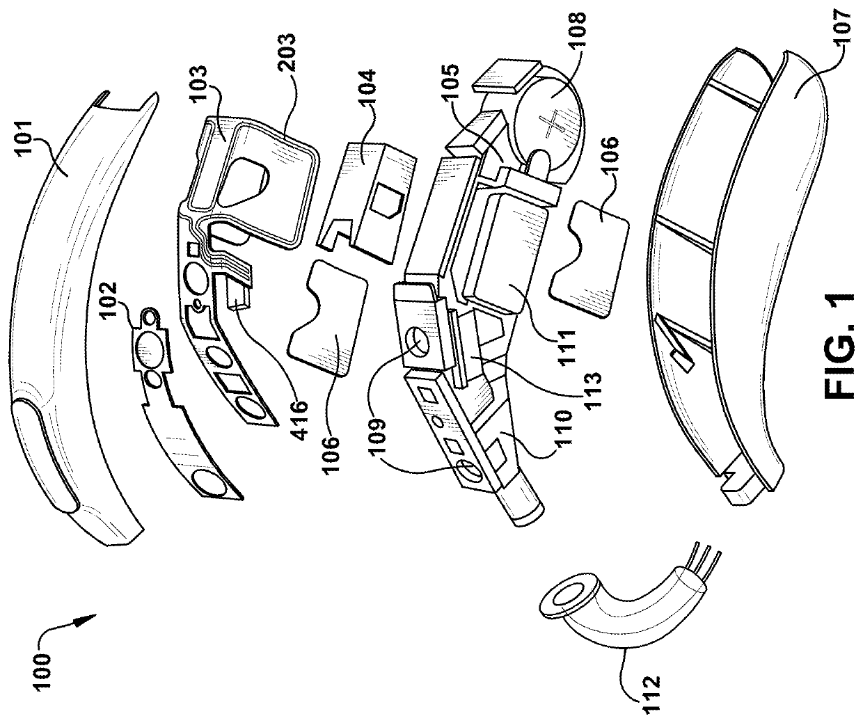
[0041]FIG. 1 is exploded view illustrating several parts of a hearing device component. The illustrated hearing device is a behind-the-ear (BTE) component 100 of a hearing aid. Other hearing device components may include, for example, an in-the-ear (ITE) component of a hearing aid, an earbud, or an earphone...


PUM


Abstract

A hearing device includes a wireless communication unit, such as a radio frequency transceiver, and a two-half loop antenna. The antenna includes a conductor defining a first half loop and a second half loop configured to be fed in series with a radio signal from a radio frequency transceiver. The first half loop and the second half loop have mirror images forming respective half loops of the two-half loop antenna. Transverse segments of the first half loop and second half loop join the first half loop and the second half loop at a mid-point of the antenna near a feeding point. The physical antenna length of the antenna is less than ¾ of the wavelength of the radio frequency signal to be transmitted or received through the antenna. An electrical length of the antenna is approximately equal to the wavelength of the radio frequency signal to be transmitted or received.

Description

FIELD OF INVENTION[0001]The present disclosure relates to the field of hearing devices, such as hearing aids, having antennas adapted for wireless communication, such as for wireless communication with a hearing device accessory and / or one or more hearing devices.BACKGROUND OF INVENTION[0002]Hearing devices, such as hearing aids, earphones, and earbuds, for example, are tiny, delicate devices comprising many electronic and metallic components contained in a housing small enough to fit at least partially in the ear canal of a human or behind the outer ear. Several electronic and metallic components in combination with a small size of the hearing device housing impose several design constraints on radio frequency antennas to be used in hearing aids possessing wireless communication capabilities. Further, the antenna in the hearing device has to be designed to achieve a satisfactory antenna gain despite the size limitation and other design constraints.[0003]An antenna converts electric...

Claims


Application Information

Patent Timeline
IPC IPC(8): H04R25/00H01Q7/00H01Q1/27
CPCH04R2225/51H01Q1/273H01Q7/005H04R25/554H01Q1/24H01Q1/38H01Q1/50H04R3/00H01Q7/00H04R1/1091H04R2420/07H04R25/609
Inventor PERRI, ANTONIOOESCH, YVESCALLIAS, FRANCOIS
Owner SONOVA AG
Why Eureka
Try Eureka