Clock fractional divider module, image and/or video processing module, and apparatus

Active Publication Date: 2020-10-08
ROBERT BOSCH GMBH
View PDF0 Cites 1 Cited by
  • Summary
  • Abstract
  • Description
  • Claims
  • Application Information

AI Technical Summary

Benefits of technology

The present invention provides a clock fractional divider module with a dual-core lock step unit that can detect, recognize, and correct errors more reliably. This helps to improve the accuracy and reliability of the clock fractional division process.

Problems solved by technology

In such architectures, however, handling of common-cause faults or failures leading to major system failures is—in general—still not completely satisfying.

Method used


Image

  • Clock fractional divider module, image and/or video processing module, and apparatus
  • Clock fractional divider module, image and/or video processing module, and apparatus

Examples


Embodiment Construction

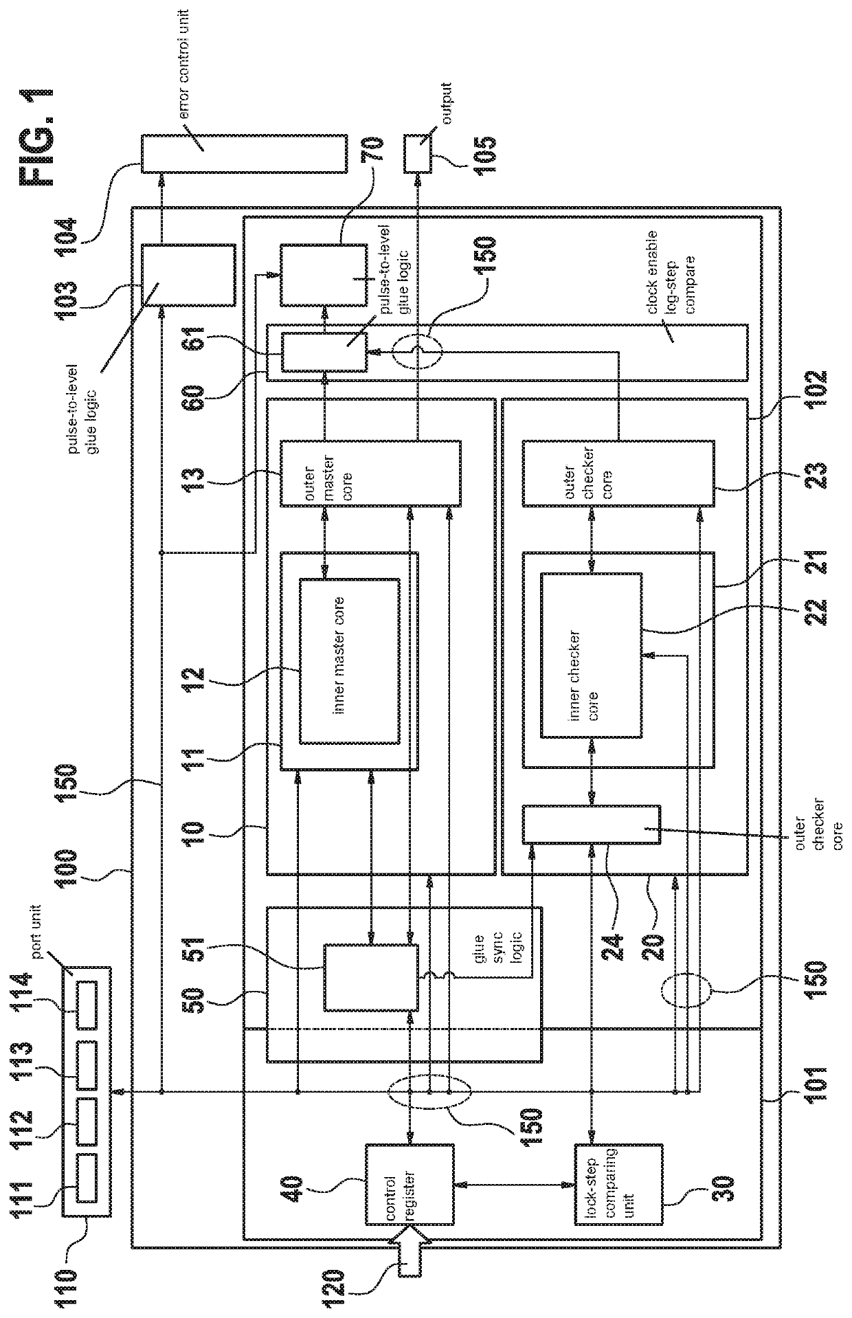
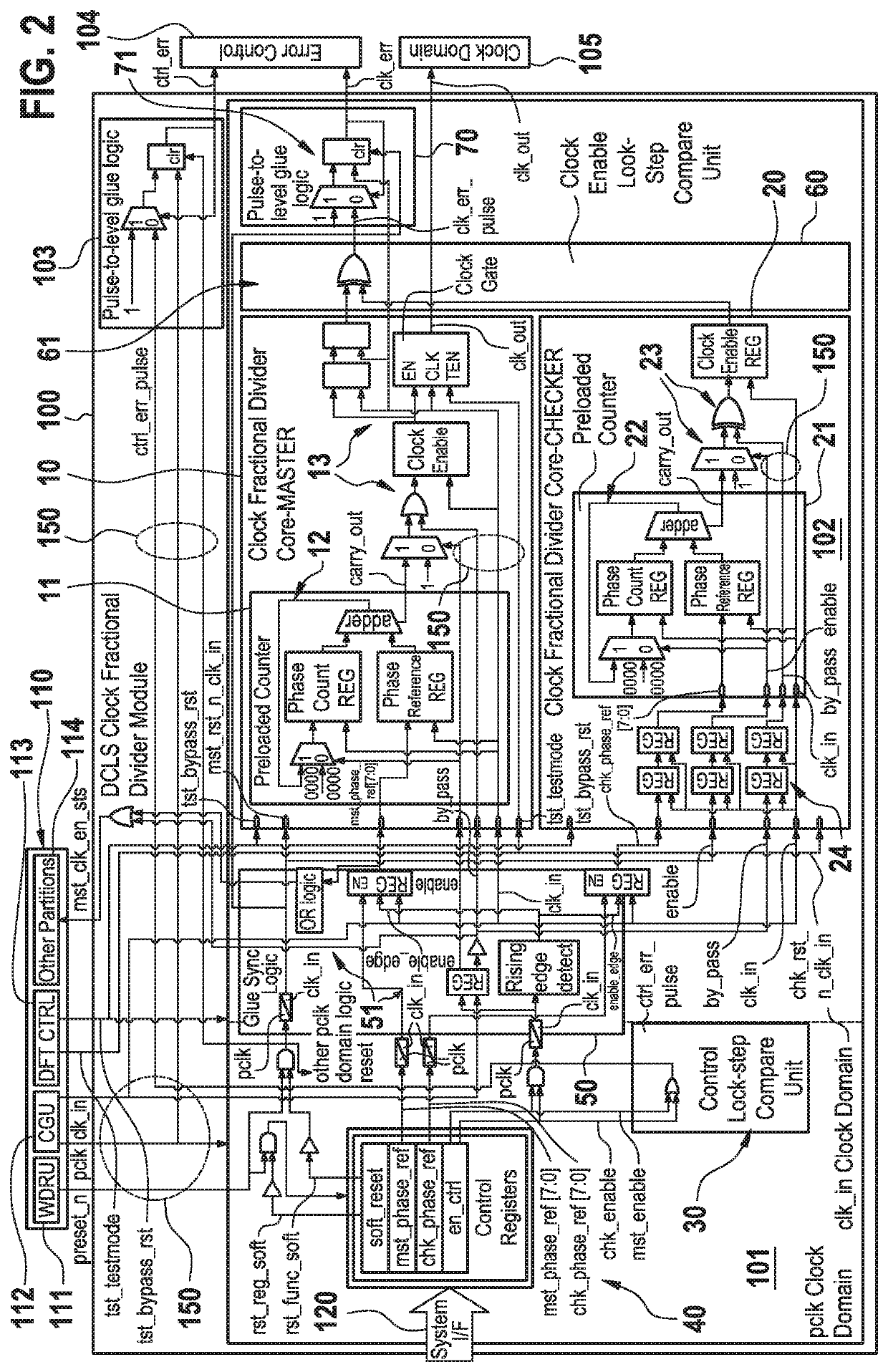
[0023]Below, example embodiments and the technical background of the present invention are described in detail by taking reference to accompanying FIGS. 1 and 2. Identical or equivalent elements and elements which act identically or equivalently are denoted with the same reference signs. Not in each case of their occurrence a detailed description of the elements and components is repeated.

[0024]The depicted and described features and further properties of the invention's embodiments can arbitrarily be isolated and recombined without leaving the gist of the present invention.

[0025]The main aspects of the present invention as summarized above and further features thereof, as well as properties and advantages of the present invention will be further discussed in the following by taking reference, but not restricted to, to FIGS. 1 and 2.

[0026]These figures by means of schematic block diagrams illustrate preferred embodiments of clock-fractional divider modules 100 according to the prese...


PUM


Abstract

A clock fractional divider module which is formed as, comprises or has integrated therein a dual-core lock step unit. The dual-core lock step unit is configured in order to realize a clock fractional division arrangement, mechanism or process accompanied by an error detection, recognition and / or correction arrangement, mechanism or process.

Description

CROSS REFERENCE[0001]The present application claims the benefit under 35 U.S.C. § 119 of European Patent Application No. EP 19290020.7 filed on Apr. 5, 2019, which is expressly incorporated herein by reference in its entirety.FIELD[0002]The present invention relates to a clock fractional divider module, an image and / or video processing module, and an apparatus, in particular a vehicle.BACKGROUND INFORMATION[0003]In many technical fields involving integrated circuit design, clock fractional divider modules are involved for establishing compliance of the required system processing performance in view of the limitation of hardware design complexity, costs and power consumption. In such architectures, however, handling of common-cause faults or failures leading to major system failures is—in general—still not completely satisfying.SUMMARY[0004]An example clock fractional divider module according to the present invention may have the advantage of more reliably detecting, recognizing and / ...

Claims


Application Information

Patent Timeline
IPC IPC(8): G06F11/07G06F1/08
CPCG06F11/0751G06F11/0733G06F1/08G06T1/20H03K21/026H03K21/10H03K21/18H03L7/1803G06F11/1604G06F11/1608
Inventor EYCHENNE, CHRISTOPHEPIERGENTILI, DANILOCOUPE, DAVIDMONTALBANO, GIUSEPPE
Owner ROBERT BOSCH GMBH
Why Eureka
Try Eureka