
Bone plate for epiphysiodesis

Active Publication Date: 2020-10-15
ORTHOFIX SRL
View PDF0 Cites 0 Cited by
  • Summary
  • Abstract
  • Description
  • Claims
  • Application Information

AI Technical Summary

Benefits of technology

The present invention provides a bone plate with a recess that allows for increased flexibility and permissible divarication range of screws without compromising the manufacturing process. The bone plate has first and second openings that are identical and opposite each other, which merges with the cup-shaped seat for housing the head of the fixing screw. This design allows for better access to the surgery area without risking damage to the plate with surgical tools. The bone plate is made from a single piece of rigid, non-pliable material, such as titanium.

Problems solved by technology

A significant drawback relates in particular to the risk of the fixing screws breaking during the bone realignment process.
This causes a bending stress that can lead to breakage of the screw.
In fact, in some cases, the angle permitted by the screws is not sufficient to ensure full correction of the bone deformity with a single surgery, and the screws must be repositioned once they have reached the abutment position previously identified.
Moreover, as well as a remarkable increase in manufacturing costs, this solution presents further disadvantages related to the lateral projection of the hinge element, which defines an additional encumbrance of the device as this can trigger an inflammatory process in the surrounding soft tissue.
These annular recesses require complex machining and may hinder plate resistance and compactness.

Method used


Image

  • Bone plate for epiphysiodesis
  • Bone plate for epiphysiodesis
  • Bone plate for epiphysiodesis

Examples


first embodiment

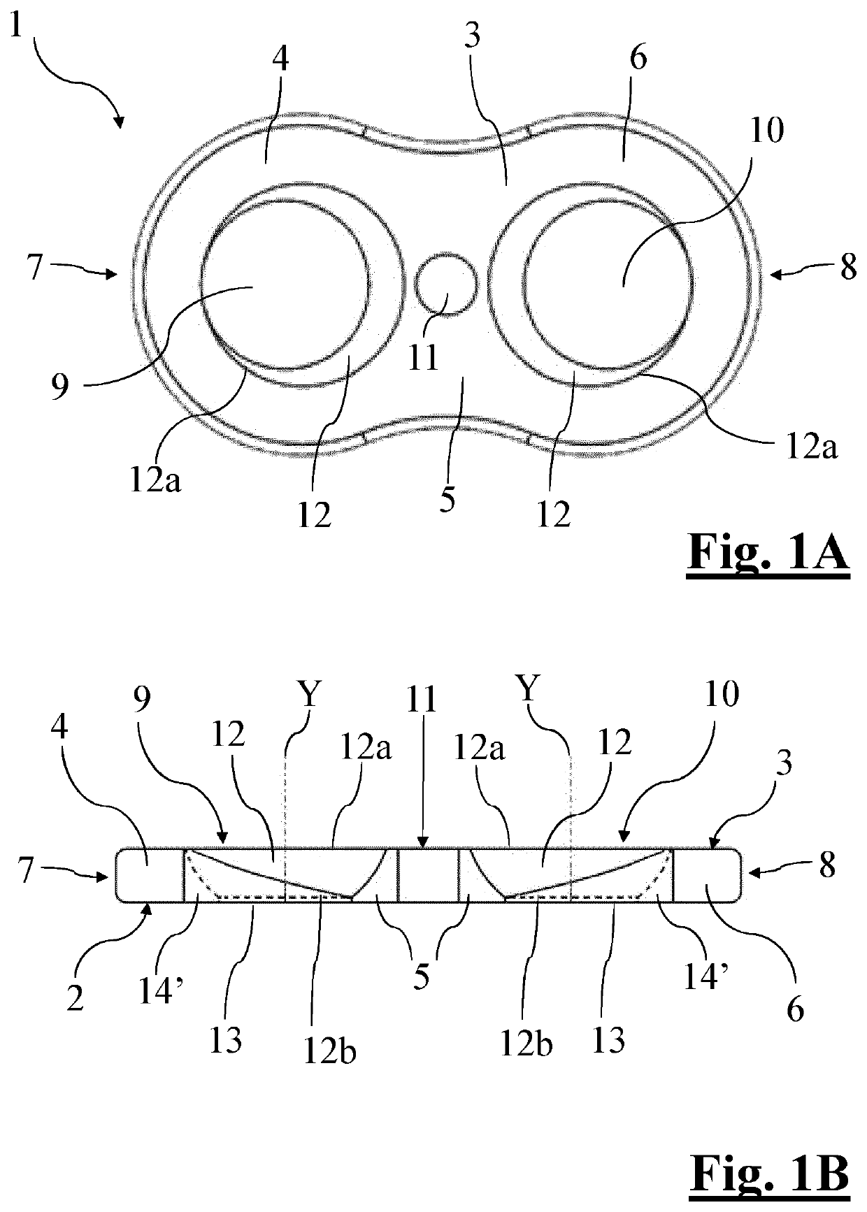
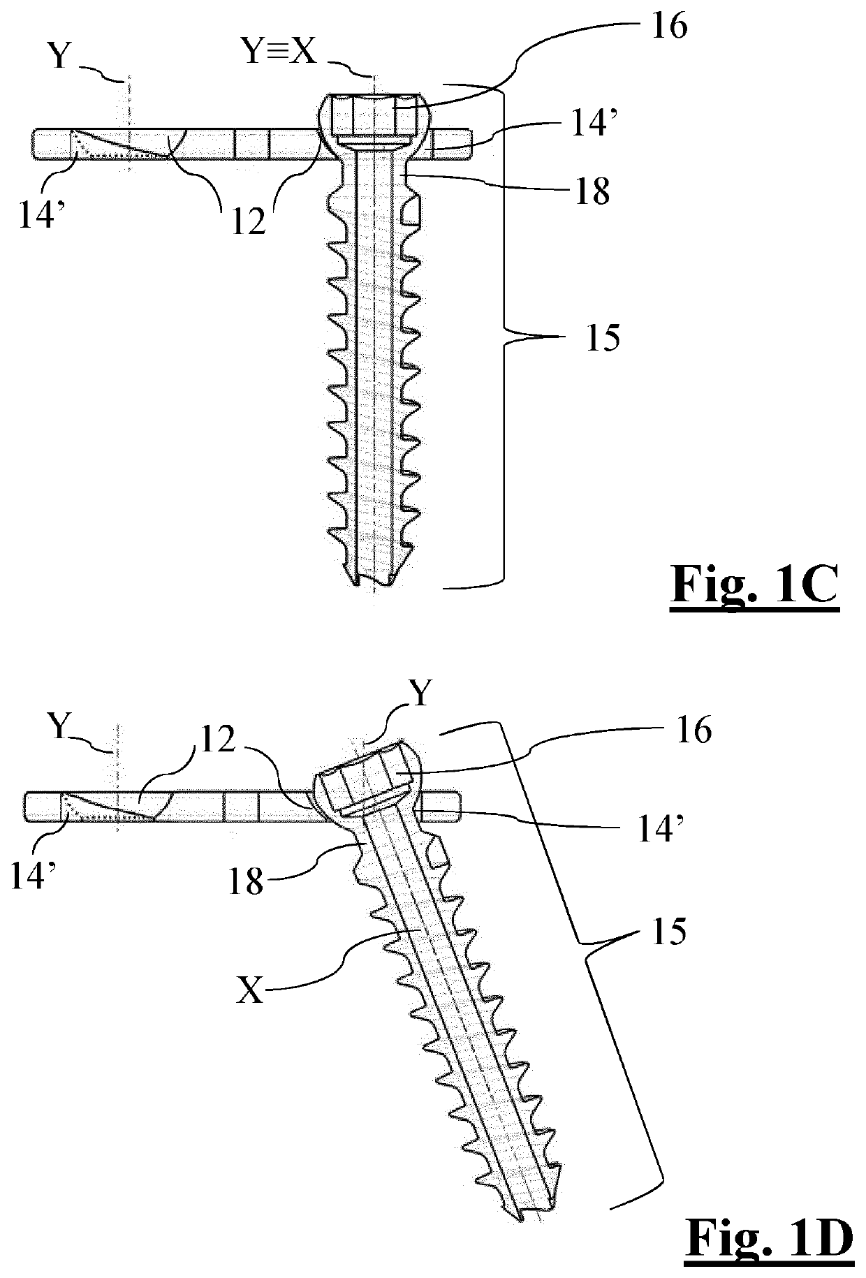
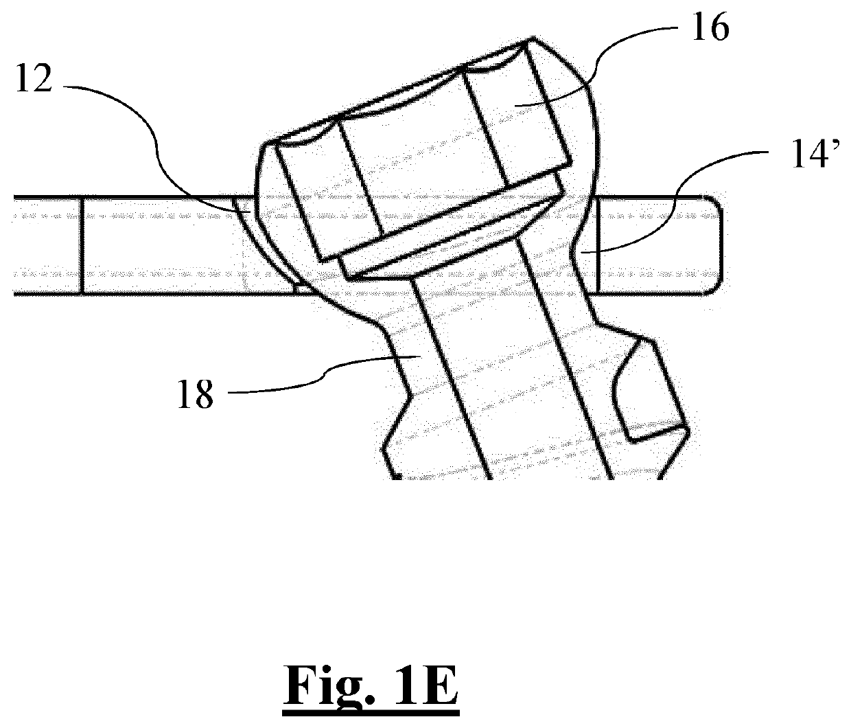
[0090]A first embodiment described in FIGS. 1A-1E shows a recess hereafter referred to as an eccentric recess 14′.

[0091]The eccentric recess 14′ is defined by a hole, with a parallel axis and a diameter which is smaller than that of the entry section 12a of the cup-shaped seat 12. The hole is tangent to the outermost edge (i.e. closer to the respective end 7, 8 of the first 9 and second opening 10) of said entry section 12a.

[0092]The hole of the eccentric recess 14′ therefore defines a cylindrical widening, orthogonal to the bone plate 1, of the external periphery of the cup-shaped seat 12a, also defining an eccentric widening of the cylindrical hole 13 which in this embodiment is completely contained in the geometry of recess 14′.

[0093]Said eccentric recess 14′ is created by means of boring and slotting, creating a cylindrical through hole with a diameter which is smaller than that of the entry section 12a, with an axis parallel to axis Y of the cup-shaped seat 12, and being tange...

second embodiment

[0094]A second embodiment described in FIGS. 2A-2E shows a recess hereafter referred to as a slot-shaped recess 14″.

[0095]The slot-shaped recess 14″ is defined by a hollow which has a depth lower than the bone plate 1 thickness, and which extends lengthways from one point on the plate at one end 7, 8 to merge with the channel defined by the cup-shaped seat 12 and the cylindrical hole 13. The width of said hollow is preferably the same as the diameter of the cylindrical hole 13 that it connects with.

[0096]The slot-shaped recess 14″ is formed by removing material from the area surrounding the cup-shaped seat 12 at the end 7, 8. Such removal of material is achieved by means of face milling the bone plate 1 so as to create a lengthways hollow with semi-circular end which extends from the area close to the end 7, 8 and merges in the cup-shaped seat 12 and the cylindrical hole 13 below.

third embodiment

[0097]A third embodiment described in FIGS. 3A-3C shows a recess hereafter referred to as a tilted cylindrical hole recess 14′″.

[0098]The tilted cylindrical hole recess 14′″ is defined by a hole which merges within the cup-shaped seat, whose diameter is greater or at least the same as the diameter of the top non-threaded section 18 of the shank of the fixing screw 15 and which has an axis Z tilted by angle β with respect to axis Y of the opening 9, 10. The hole opens on the outer side periphery of the cup-shaped seat 12 and extends downwards and outwards, i.e. towards the respective end 7, 8, and emerges on the bottom surface 2 of the plate. The hole is merged with the cylindrical hole 13 for its entire length.

[0099]The tilted cylindrical hole recess 14′″ is formed by removing material from the area surrounding the cup-shaped seat 12 at the end 7, 8 by means of a boring operation.


PUM


Abstract

The present invention relates to a bone plate (1, 21) for epiphysiodesis, which has been advantageously improved to in allow better articulation of the fixing screws engaged with the bone plate (1, 21), comprising: a first portion (4) and a second portion (6) joined by a connecting portion (5), intersected by a first (9) and a second opening (10), respectively, structured to receive the same number of fixing screws; the bone plate having a bilobal figure, such as an eight shape; at least one of said first (9) and second (10) openings comprising: a cup-shaped seat (12) for housing a fixing screw head in a tillable manner, and at least one recess (14″) which merges into the cup-shaped seat (12) expanding an exit section (12b) away from the connecting portion (5).

Description

FIELD OF APPLICATION[0001]The present invention relates to an implantable device for correcting angular deformities of long bones, such as genu varum and genu valgum, and in particular a bone plate for epiphysiodesis operations applied at the ends of deformed bones in paediatric patients.[0002]The invention can therefore be applied mainly in the paediatric orthopaedics field, and the following description is made with reference to, but not limited to, use within this field.PRIOR ART[0003]In the technical sector relating to this invention, the use of staples or plates is recognised for limiting or impeding growth at a particular point of the growth plate at the end of a long bone with an angular deformity in paediatric patients. The physiological process of physeal tissue growth, which remains unhindered on the opposite, non-instrumented side, promotes gradual axial realignment of the bone.[0004]In the specific case of using a bone plate, the plate is positioned using fixing screws w...

Claims


Application Information

Patent Timeline
IPC IPC(8): A61B17/80
CPCA61B17/8014A61B17/8061A61B17/80
Inventor VENTURINI, DANIELEMAGNI, MARCOZACCARIA, ANDREA
Owner ORTHOFIX SRL
Learn More