Heat dissipating module with three-dimensional structure

a heat dissipating module and three-dimensional technology, applied in the direction of basic electric elements, lighting and heating apparatus, electrical apparatus, etc., can solve the problems of ineffective heat dissipation results, inability to achieve certain efficiency, and high temperature of devices during operation, so as to achieve less side effects, high power rate, and heat dissipation efficiency.

Inactive Publication Date: 2020-10-15
JAI LONG PING TANG TECH
View PDF0 Cites 1 Cited by
  • Summary
  • Abstract
  • Description
  • Claims
  • Application Information

AI Technical Summary

Benefits of technology

[0014]Based on the thermosyphon effect and the principles of Boyle's Law, the present invention has the vapor flow upwards to the heat dissipating cavity rapidly and evenly through the vapor guiding chamber to be projected from the projecting exit. And the structure of the heat dissipating cavity being arranged at a distance from the heat source features even greater efficiency in heat dissipation and less side effects to the products it is installed on during operation. The present invention is thereby suitable for LED lighting fixtures and electronic devices with high power rates.

Problems solved by technology

As technology advanced, nowadays the chips installed on electronic devices have increased, causing higher temperature of the devices during operations.
Although such operation can dissipate the heat in some degree, it cannot achieve certain efficiency since the rear end of the pipe 11 has the worst thermal conductivity.
On the other hand, due to the design of the pipe 11, the working fluid inside the pipe 11 would stay at the rear end when going through phase changes, and the thermal energy cannot be conducted and transferred to the fins 12 effectively, causing ineffective results of the dissipation.

Method used


Image

  • Heat dissipating module with three-dimensional structure
  • Heat dissipating module with three-dimensional structure
  • Heat dissipating module with three-dimensional structure

Examples


Embodiment Construction

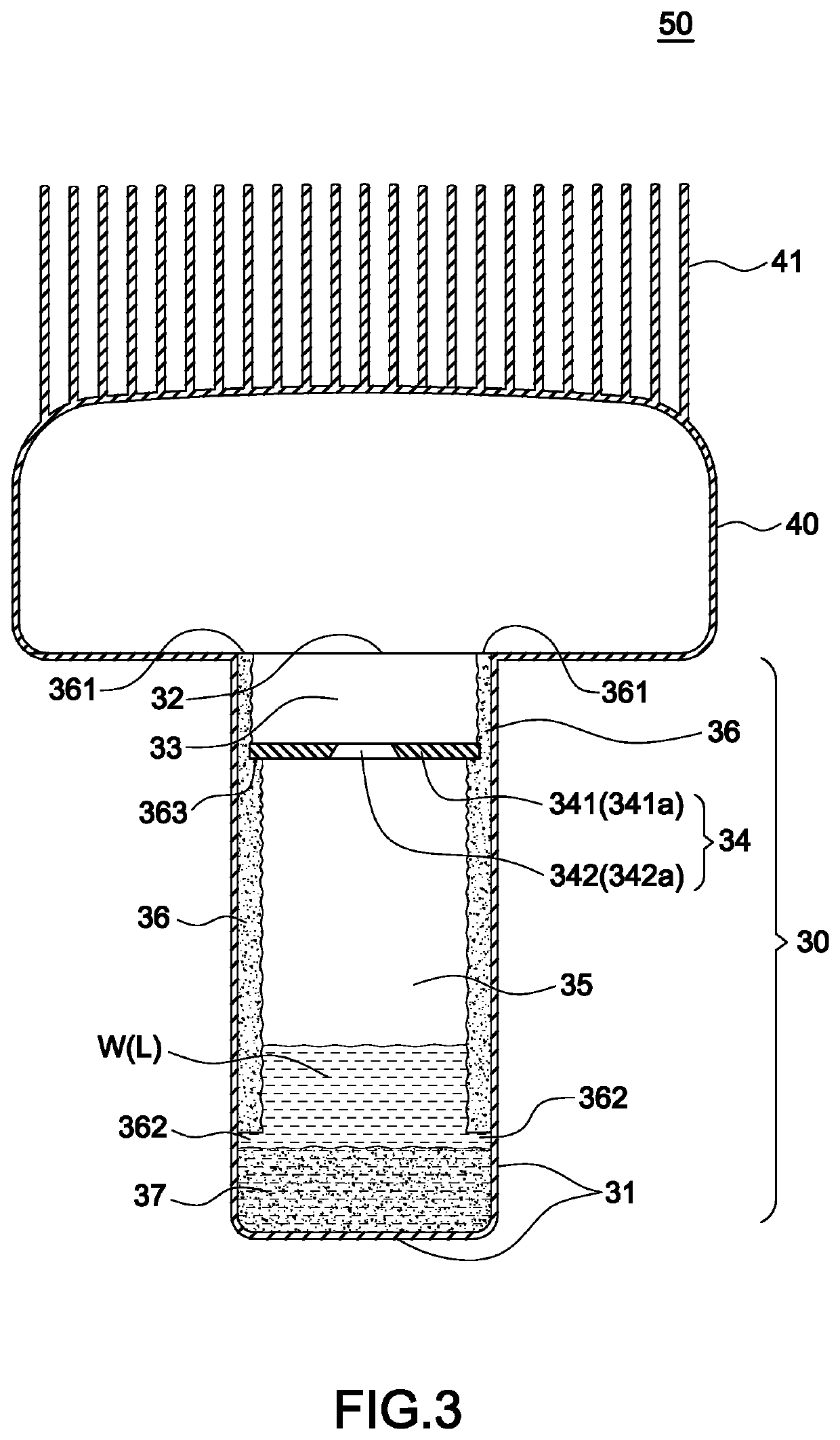
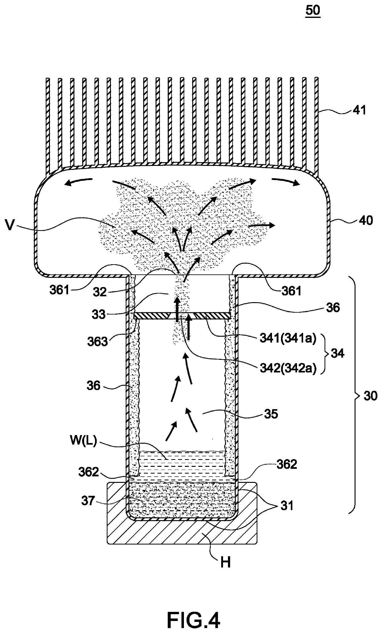
[0025]Referring to FIGS. 3-6, in a first applicable embodiment, a heat dissipating module with micro-passages 50 mainly includes a heat absorbing cavity 30, a vapor guiding section 34, a heat dissipating cavity 40 and at least a layer of capillary structure 36.

[0026]The heat absorbing cavity 30 is vertically arranged as a bottom section 31 thereof arranged to be contacted with a heat source H and a first opening 32 arranged at a top section thereof to form a connecting space 33 between the bottom section 31 of the heat absorbing cavity 30 and the first opening 32. In this embodiment, the bottom section 31 includes a bottom surface and a periphery extended upwards from the bottom surface in order to be contacted with different heat sources.

[0027]The vapor guiding chamber 34 is arranged in the connecting space 33 near the first opening 32 and includes a cover board 341 arranged in a shape corresponding to an inner periphery of the connecting space 33 for the cover board 341 to be fixe...


PUM


Abstract

A heat dissipating module with three-dimensional structure includes a heat dissipating cavity connecting to a top of a heat absorbing cavity to form a distance from a heat source. When a working fluid in the heat absorbing cavity absorbs the thermal energy and is vaporized, the vapor would flow up to a vapor guiding space due to thermosyphon effect and principles of Boyle's Law, and then the vapor is projected and spread rapidly and evenly to the heat dissipating cavity through a projecting exit. Then the vapor is condensed into liquid and become the working fluid again by heat exchange. The condensed liquid then drips down and flows back to the heat absorbing cavity via micro-passages, forming a cycle of phase change of the working fluid for operation of heat dissipation.

Description

BACKGROUND OF THE INVENTION1. Field of the Invention[0001]The invention relates to a heat dissipating module, especially to one that has a three-dimensional structure and forms a distance from the heat source to the dissipating fins.2. Description of the Related Art[0002]As technology advanced, nowadays the chips installed on electronic devices have increased, causing higher temperature of the devices during operations. To avoid problems resulted from high temperature, heat pipes are commonly used in the field for heat dissipation. Such heat pipes conduct and transfer the thermal energy by the latent heat produced from phase changes of the working fluids. At the vaporization section of the heat pipes, the working fluids obtain a huge amount of thermal energy from the heat source by vaporizing the latent heat and then release the thermal energy and condense into liquid at the condensation section of the heat pipes. The working fluids would flow back to the vaporization section due to...

Claims


Application Information

Patent Timeline
Patent Type & Authority Applications(United States)
IPC IPC(8): F28D15/02F28D15/04F28F13/08
CPCF28D15/025F28D15/0233F28F13/08F28D15/04H01L23/427H01L23/467H01L23/4336H01L23/367
Inventor LAN, HAI
Owner JAI LONG PING TANG TECH
Why Eureka
Try Eureka