Visor assembly

a technology of visors and components, applied in the field of visor assemblies, can solve the problems of leaking into sealed chambers, affecting the optical quality of the final product, and affecting so as to improve the performance of the visor assembly, constant force, and constant depth

Pending Publication Date: 2020-10-22
PINLOCK PATENT
View PDF11 Cites 2 Cited by
  • Summary
  • Abstract
  • Description
  • Claims
  • Application Information

AI Technical Summary

Benefits of technology

[0049]The spacer is preferably integrally formed into the overlay-shield by mechanical deformation of the overlay-shield. This can be done, for example, by mechanical deformation, preferably thermally, with a mould. That is, a sheet-like overlay-shield can be provided with a protrusion in a simple manner via mechanical deformation.
[0050]The protrusion that forms the integrally formed spacer, is preferably formed as a continuous channel running around a central zone of the inner shield. The central zone encompasses the viewing area of the overlay-sheet. The continuous channel preferably has a substantially constant depth. Because the channel is continuous and runs around a central zone of the shield, and because the channel has a substantially constant depth, it will be possible to press the inner shield against the outer shield in a manner such that the central zone is sealed airtightly from the surrounding area. An insulating effect is hereby obtained, which can improve the performance of the visor assembly in extreme conditions. The substantially constant depth is defined here as a depth which does not change, or does so only very gradually. Owing to a gradual change in the depth the protrusion will still be able to lie against the outer shield in continuous manner and with a constant force, When change is gradual, the depth will therefore also be considered as being substantially constant. On the basis of this definition it will be apparent that an embodiment wherein the protrusion has a depth of 3 mm at the position of a first segment of the periphery, this protrusion decreasing gradually over a second segment of the periphery to a depth of 1 mm and then gradually becoming deeper again via a third segment, is also deemed an embodiment with substantially constant depth.

Problems solved by technology

With such a process a number of problems occur.
The overlap at the start and finishing points for laying down the bead can cause problems with regards to optical quality of the final product as well as causing leakages into a sealed chamber because of a thickening or thinning of the bead at these points.
The withdrawing of the nozzle can also lead to fowling of the nozzle.
The thickness and height of the completed set silicone bead cannot be guaranteed because the bead of silicone resin sets and flows differently according to the environmental conditions.
If the drying room is not a clean room free of dust particles, these particles will irremovably ingress to the unset silicone resin.
This leads to a poor optical quality of the set silicone and potentially poor sealing qualities.
For these reasons the currently dominant manufacturing process can be overly time consuming and too often produce a less than perfect spacer or seal
While such techniques can provide excellent seals and spacers, and answer at least some of the above concerns, the manufacturing can be complex and not readily diversified to an extended product line up of varying visor shapes.
This can be problematic for a number of reasons that can depend upon the use to which the visor assembly is put, e.g. for motorcycle riding.
For example, any play between components can lead to irritating noise and abrasion e.g. of the viewing region of the visor, and ultimately to the overlay-visor coming free from its attachments.
While an apparent route to answering such a problem would be to more solidly affix the inner-visor to an outer-visor, e.g. by use of bolts or screws, these solutions can be undesirable because of increased complexity and user inconvenience.

Method used


Image

  • Visor assembly
  • Visor assembly
  • Visor assembly

Examples


Embodiment Construction

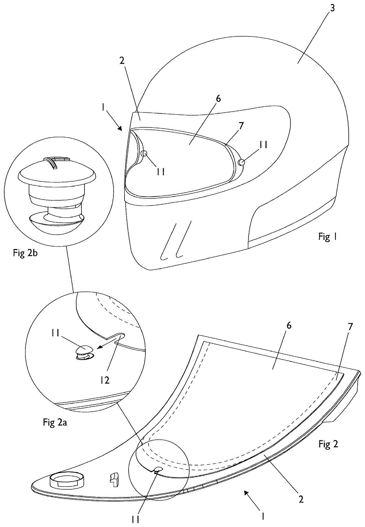
[0067]FIG. 1 shows a motorcycle helmet having an opaque skull protecting portion 3 to which is attached a 3D visor assembly 1. There is provided a shield-visor 2 having releasably attached to its inner-surface an overlay-visor 6. The overlay-visor 6 is releasably attached to the shield-visor 2 by mechanical fastenings 11 at opposed ends of the shield-visor 2.

[0068]One of the mechanical fastenings 11 can be seen more clearly in FIGS. 2, 2a and 2b. It is comprised of an eccentric pin 11 fitted to the shield-visor 2. The overlay-visor 6 is provided with a recess 12 that mates with the eccentric pin 11. The mechanical fastenings 11 hold the overlay-visor 6 under tension within the inner curve of the shield-visor 2, that is the overlay-visor 6 is compressed between the pins 11. The eccentric pins 11 of this embodiment are rotatable into and out of engagement with the recesses 12 of the overlay-visor 6 in order to ensure a secure retention thereof. In the event that the overlay-visor 6 sh...


PUM


Abstract

There is provided a visor assembly (1), preferably for the motorcycle helment, comprising a shield-visor (2) having a surface, an overlay-visor (6) adapted to be releasably attached to the shield-visor, the overlay-visor comprising a viewing area, an integrally formed spacer (7) extending along at least a portion of a periphery of the viewing area, and a gasket (8) upon a distal surface of the spacer; and a mechanical fastening (11) releasably attaching the overlay-visor to the surface of the shield-visor.

Description

BACKGROUND OF THE INVENTION1. Field of the Invention[0001]The invention relates generally to visor assemblies that comprise an overlay-sheet and a shield-visor, which overlay-sheet and shield-visor are releasably attached to one another; and a kit of parts for constructing such a visor assembly.[0002]The invention may also or alternatively generally relate to a visor, particularly an overlay-visor, for use in a visor assembly in which an overlay-visor and a shield-visor are releasably attached to one another.[0003]The visors and visor assemblies of the invention are particularly useful for personal protection equipment for facial and eye protection. Examples of preferred personal protection equipment include motorbike helmets, motorbike style helmets such as quad-bike, snowmobile, racing car and skiing helmets; heavy-duty protective visors, for example, ballistic face shields which may be used in riot helmets and visors for use by the emergency services; and / or goggles such as under...

Claims


Application Information

Patent Timeline
Patent Type & Authority Applications(United States)
IPC IPC(8): A42B3/22A42B3/24
CPCA42B3/221A42B3/24A42B3/226
Inventor LIPKENS, PAUL WILHELMUSDE BOER, HERMAN
Owner PINLOCK PATENT
Why Eureka
Try Eureka