Unicouple Based Flexible Thermoelectric System

Inactive Publication Date: 2020-10-22
MAGNA SEATING
View PDF0 Cites 0 Cited by
  • Summary
  • Abstract
  • Description
  • Claims
  • Application Information

AI Technical Summary

Benefits of technology

The patent text describes a thermoelectric system that uses a foam seat pad with a thermoelectric circuit. The circuit is made up of small units that are pressed into the foam and comprise heat sinks. The system is designed to improve airflow and prevent leakage, and can be integrated into a variety of products like car seats or office chairs. The technical effect of this system is to provide efficient and effective heating or cooling for the user's body.

Problems solved by technology

Also, channels in the foam to provide airflow across heat sinks may leak air out of the channels.
Further, when two layers of foam are used to form a foam pad, the layers may separate under load or over time.

Method used


Image

  • Unicouple Based Flexible Thermoelectric System
  • Unicouple Based Flexible Thermoelectric System
  • Unicouple Based Flexible Thermoelectric System

Examples


first embodiment

[0026]According to the present disclosure, the upper foam 66 and the main foam 74 may comprise conventional polyurethane foam having densities suitable for an intended application. The upper foam 66 and the main foam 74 may have different densities, similar densities, and / or may be comprised of different foam materials. Likewise, any suitable adhesive may be used to adhere the upper foam 66 with the main foam 74.

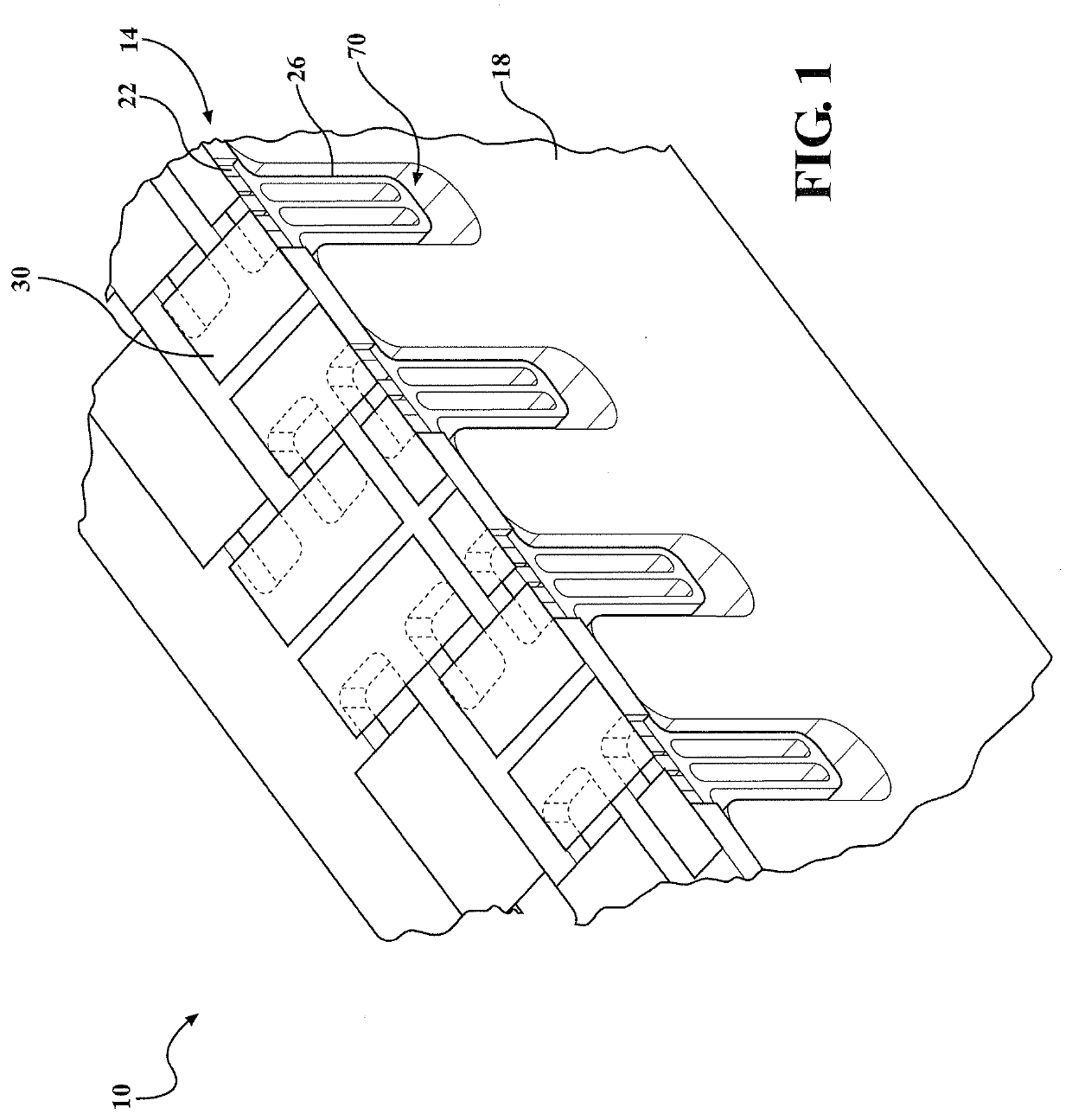
[0027]FIGS. 5 and 6 illustrate a side view and a top perspective view, respectively, of the thermoelectric circuit 14 assembled with the foam pad 58 according to one embodiment of the present disclosure. The thermoelectric circuit 14 containing the plurality of unicouples 22 may be integrated into the seat foam pad 58 by pressing the unicouples 22 with heat sinks 26 through the insertion holes 68 in the upper foam 66 and into the airflow channels 70 in the main foam 74. Generally, the unicouples 22 may be positioned within, above, below, and / or partially within the insertion...

second embodiment

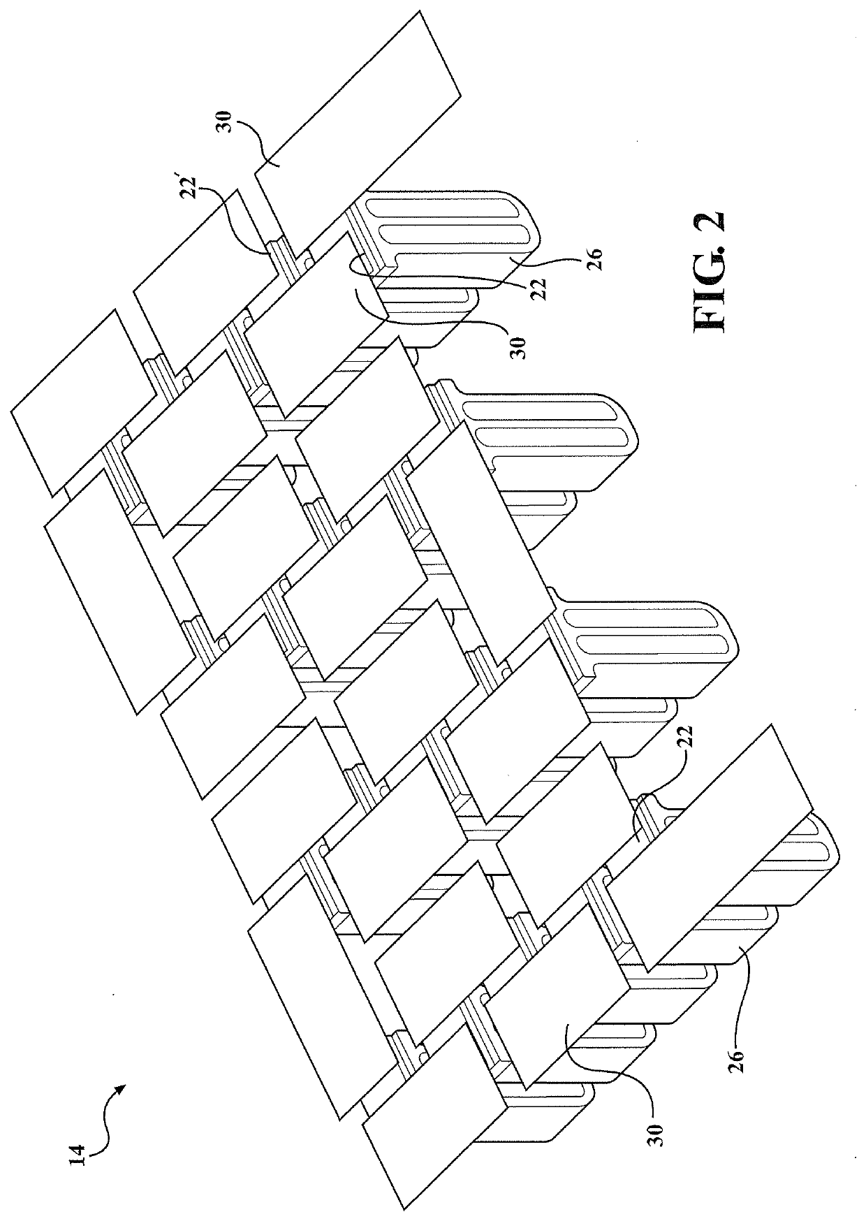
[0032]FIGS. 8 and 9 illustrate a side view and a top perspective view, respectively, of the thermoelectric circuit 14A assembled with the foam pad 58A according to the present disclosure. The thermoelectric circuit 14A containing the plurality of unicouples 22A may be integrated into the seat foam pad 58A by pressing and / or inserting the unicouples 22A with heat sinks 26A through the insertion holes 68A in the upper foam 66A and into the airflow channels 70A in the upper foam 66A. Generally, the unicouples 22A may be positioned within, above, below, and / or partially within the insertion holes 68A in the upper foam 66A after the unicouples 22A are inserted through the insertion holes 68A.

[0033]Each airflow channel 70A is generally sized such that the width and depth of the airflow channel 70A is greater than the width and length of an individual heat sink 26A. Thus, when the heat sink 26A is pressed into the airflow channel 70A, there is airflow space between the heatsink outer walls...

third embodiment

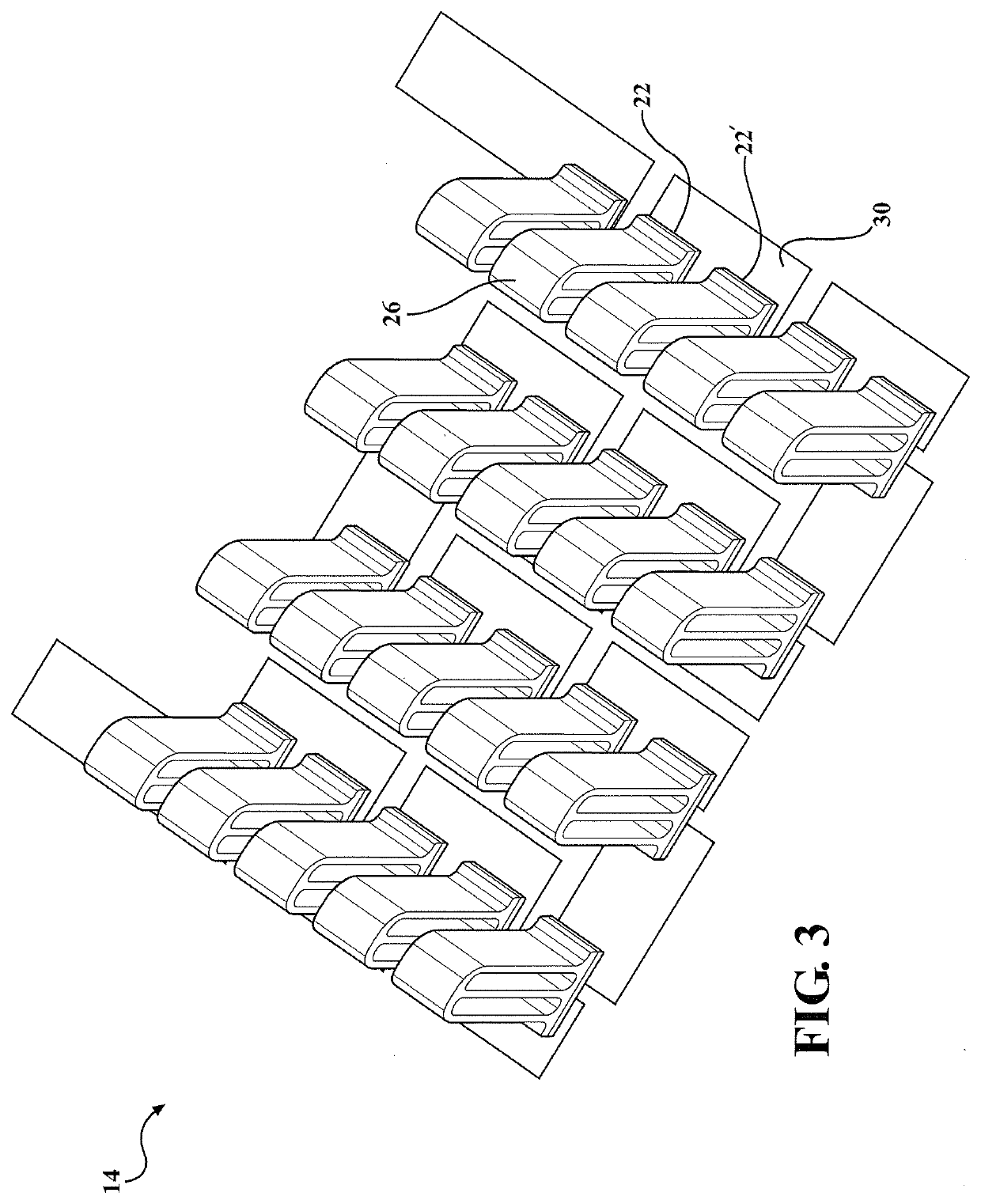
[0035]the present disclosure integrating a thermoelectric circuit 14B into a seat foam pad 58B is generally shown in FIGS. 10-12. FIG. 10 illustrates a top perspective view of the seat foam pad 58B which comprises an upper foam 66B assembled to a base foam 74B. Airflow channels 70B, 70W and insertion holes 68B, 68W may be partially or fully integrated into the upper foam 66B. Opposing airflow channel sidewalls 98B, 102B, 98B′, 102W may be formed within the upper foam 66B. The sidewalls 98B, 102B, 98W, 102W may abut adjacent surfaces with generally a right angle corner 110B, or alternatively, the corners 110B may have a radius, bevel, taper, or other contours suitable for an intended application. Partition walls 118B in the upper foam 66B separate each of a plurality of adjacent airflow channels 70B, 70W. An exemplary foam partition wall 118B extends between one sidewall 102W of the airflow channel 70W and an adjacent sidewall 98B of the airflow channel 70B. The partition walls 118B ...


PUM


Abstract

A unicouple based thermoelectric system comprises a thermoelectric circuit integrated into a cellular foam seat pad. The foam seat pad comprises an upper foam layer and a main foam layer. The thermoelectric circuit comprises a plurality of unicouples with heat sinks which may be pressed through insertion holes in the upper foam into airflow channels in the main foam. The upper foam seals the air channels from leakage which improves the airflow across the heat sinks. Further, the upper foam may be interlocked with the main foam. Alternatively, the upper foam may comprise the insertion holes and a portion of the airflow channels.

Description

CROSS-REFERENCE TO RELATED APPLICATIONS[0001]This application claims priority to U.S. Provisional Application No. 62 / 579,910, filed on Nov. 1, 2017.BACKGROUND OF THE INVENTION1. Field of the Invention[0002]The present invention relates to a seat assembly in an automotive vehicle having a heating and cooling mechanism or device. More particularly, the invention relates to a unicouple based flexible thermoelectric system assembled with a cellular foam pad, which improves airflow across the heat sinks and reduces leakage from air channels.2. Description of Related Art[0003]Automotive vehicles include one or more automotive seat assemblies having a seat cushion and a seat back for supporting a passenger or occupant above a vehicle floor. It is commonly known to provide heating and / or cooling within a seat assembly for seat occupant comfort. For example, heating and / or cooling thermoelectric elements may be integrated into the seat assembly. One example is a thermoelectric device includi...

Claims


Application Information

Patent Timeline
IPC IPC(8): B60N2/56B60N2/70F25B21/04
CPCB60N2/5621F25B2321/0251B60N2/70F25B21/04B60N2/5685B60N2/5692H10N10/13
Inventor DAVIS, JASONCOOK, MATTHEW TSTEPANOV, ARTUR
Owner MAGNA SEATING
Why Eureka
Try Eureka