A centrifugal fan collector with double arc profile

A centrifugal fan and current collector technology, which is applied in the direction of machines/engines, mechanical equipment, liquid fuel engines, etc., can solve the few problems mentioned by the current collector, achieve improved efficiency, improve aerodynamic performance, and improve fan efficiency Effect

Active Publication Date: 2021-07-27
HUAZHONG UNIV OF SCI & TECH
View PDF3 Cites 0 Cited by
  • Summary
  • Abstract
  • Description
  • Claims
  • Application Information

AI Technical Summary

Problems solved by technology

The shape of the current collector mainly has four types: cylindrical, conical, conical arc and nozzle. At present, the conical arc current collector is used more. The structure and processing technology of this type of current collector are simple and the performance is excellent. There is a large room for improvement. For the conical arc collector, most scholars' research mainly focuses on the installation gap between the impeller and the collector, the eccentric installation of the collector, the expansion angle, the contraction angle, etc., the mention of the collector The line shape of the collector will have an impact on the fluidity of the main airflow and the vortex area at the back of the collector

Method used


Image

  • A centrifugal fan collector with double arc profile
  • A centrifugal fan collector with double arc profile
  • A centrifugal fan collector with double arc profile

Examples


example 1

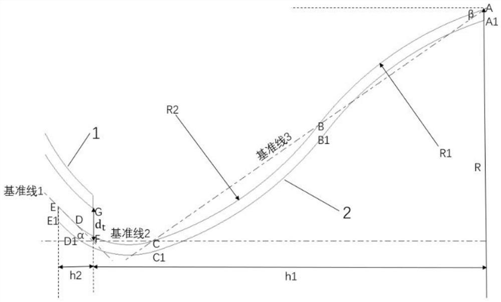
[0060] A kind of current collector design method for centrifugal fan of the present invention, specifically comprises the following steps:

[0061] Step 1, determine three baselines, the specific process is as follows:

[0062] Step 1.1, first determine the position of point A;

[0063] Such as figure 1 As shown, the radial distance from point A to the impeller rotation axis is R, and the axial distance from the impeller inlet end face is h1, and the position of point A can be determined according to R and h1;

[0064] In step 1.1, R and h1 are determined by the following formulas (1), (2):

[0065] R=(0.5)D out (1);

[0066] h1=(0.302)D out (2);

[0067] Among them, D out is the outer diameter of the impeller;

[0068] More preferably, R=0.5D out =250mm, h1=0.302D out =151mm, where D out = 500mm.

[0069] Step 1.2, determine the position of point F;

[0070] The radial distance between point F and point G on the inner wall surface of the impeller front disc 1 i...

example 2

[0090] Under different working conditions of the fan, on the basis of Example 1, keep R, h1, h2 unchanged, keep the three points of A, B, and C fixed, and change R1=R2=0.80*h1=120mm, that is, double circle The length and position of the arc chord remain unchanged, the radius of the arc is reduced, and the curvature of the double-arc line is increased. Follow the steps in Example 1 to draw the current collector line, and design a matching volute according to the changed current collector bus. Shell size parameters. Compared with Example 1, the radian of the double-arc profile line in Example 2 is significantly increased, which makes the angle between the airflow direction at the inlet and the collector profile line larger. Compared with Example 1, the curvature of the inlet section AB of the double-arc profile line increases. Small flow conditions are likely to cause the airflow to collide with the wall of the collector to form a vortex, which reduces the gentleness of the airf...

example 3

[0092] Under different working conditions of the fan, on the basis of Example 1, keep R, h1, h2 unchanged, keep the three points of A, B, and C fixed, and change R1=R2=0.90*h1=136mm, that is, double circle The length and position of the arc chord remain unchanged, the radius of the arc is increased, and the curvature of the double-arc line is reduced. Follow the steps in Example 1 to draw the current collector line, and design a matching one according to the changed current collector bus. Volute size parameters. Compared with Example 1, the radian of the double-arc line in Example 3 is reduced, and the airflow direction change angle is increased, which weakens the ability of the double-arc line to reduce the flow separation at the fan inlet, but compared with the prototype, the air flow is stable Enhanced performance, more suitable for small flow conditions.

[0093] Table 1 shows the experimental test data of the centrifugal fan with double-arc-shaped line collectors in the ...


PUM


Abstract

The invention belongs to the technical field of centrifugal fans, and discloses a centrifugal fan current collector with double-arc profiles. The bus bar of the collector adopts double-arc profiles. The transition section CD and the exit section DE are composed of: the entrance section ABC is composed of the circular arc AB and the circular arc BC tangent to point B, the transition section CD is a circular arc, and the exit section DE is a straight line section DE; the current collector bus The molded line of the inner wall surface of the busbar is the same as the molded line of the outer wall surface of the busbar. The present invention improves the shape of the current collector by controlling the outer wall profile of the busbar compared to the shape parameter settings (such as angle parameters and distance parameters) of the impeller inlet end surface, the impeller rotating shaft and three reference lines; The unique shape design and parameter setting of the profile line of the collector improves the airflow state in the collector and at the inlet of the impeller, thereby reducing the flow loss, and finally improving the efficiency of the centrifugal fan and reducing energy consumption.

Description

technical field [0001] The invention belongs to the technical field of centrifugal fans, and more specifically relates to a centrifugal fan current collector with double-arc profiles, which provides a new design method for the centrifugal fan collector. Background technique [0002] Centrifugal fans (that is, centrifugal fans) are widely used in factories, mines, tunnels and other industrial production occasions. It is a fluid machine that relies on input mechanical energy to increase the pressure of gas and transport it. The centrifugal fan mainly includes three parts: the impeller, the volute and the collector. The collector guides the gas into the impeller, the impeller pressurizes the gas, and the volute guides the gas to discharge. Scholars at home and abroad mainly focus on the impeller and volute part of the centrifugal fan research, less research on the collector. The current collector is an important part of the centrifugal fan. Its structural form changes the air ...

Claims


Application Information

Patent Timeline
Patent Type & Authority Patents(China)
IPC IPC(8): F04D29/44F04D29/66
CPCF04D29/441F04D29/667
Inventor 王军于佳鑫詹婷军杨筱沛凌杰达
Owner HUAZHONG UNIV OF SCI & TECH
Why Eureka
Try Eureka