Light module and lighting device having same

a technology of light module and lighting device, which is applied in the direction of lighting and heating apparatus, semiconductor devices for light sources, instruments, etc., to achieve the effect of improving the central improving the light uniformity and improving the luminous intensity of a surface light sour

Active Publication Date: 2020-10-22
LG INNOTEK CO LTD
View PDF0 Cites 5 Cited by
  • Summary
  • Abstract
  • Description
  • Claims
  • Application Information

AI Technical Summary

Benefits of technology

The patent text describes a lighting module that can improve the brightness and uniformity of a surface light source. It does this by using a light emitting device and a resin member with a light extraction structure. Additionally, the text mentions that the module can prevent hot spots and reduce the difference in luminous intensity between adjacent resin members. Overall, the technical effect of the patent is to enhance the performance of the lighting module.

Problems solved by technology

However, since an emitting angle of light emitted from an LED is small, when the LED is used as a vehicle lamp, it is required to increase a light emitting area of a lamp using the LED.

Method used


Image

  • Light module and lighting device having same
  • Light module and lighting device having same
  • Light module and lighting device having same

Examples


first embodiment

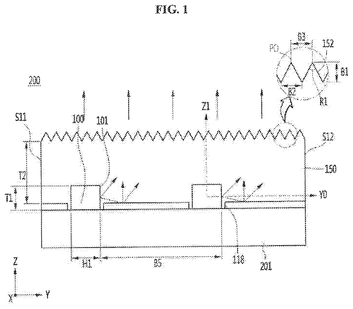
[0153]FIG. 1 is a side cross-sectional view of a lighting module according to a first embodiment, and FIG. 2 is another example of the lighting module of FIG. 1.

[0154]Referring to FIGS. 1 and 2, a lighting module 200 according to an embodiment includes a substrate 201, a plurality of light emitting devices 100 disposed on the substrate 201, and a resin member 150 covering the substrate 201 and the light emitting devices 100, and a reflective member 110 disposed between the resin member 150 and the substrate 201.

[0155]The substrate 201 includes a printed circuit board (PCB). The substrate 201 may include, for example, a resin-based circuit board (PCB), a metal core (Metal Core) PCB, a flexible PCB, a ceramic PCB, and a FR-4 substrate. When the substrate 201 is disposed in a metal core PCB disposed with a metal layer on a bottom, a heat dissipation efficiency of the light emitting device 100 can be improved. The substrate 201 may be a flexible substrate or a non-flexible substrate.

[01...

second embodiment

[0182]FIG. 9 is a side cross-sectional view of a lighting module according to a second embodiment, and FIG. 10 is a partially enlarged view of a light extraction structure of FIG. 9. In describing the second embodiment, the same configuration as that disclosed above is referred to the description disclosed above, and may be selectively applied thereto.

[0183]Referring to FIGS. 9 and 10, a lighting module 200A includes a substrate 201, a plurality of light emitting devices 100, a reflective member 110, and a resin member 160.

[0184]A first side surface S11 of the resin member 160 may be spaced apart from a rear surface of each of the light emitting devices 100. At least a portion of a second side surface S12 of the resin member 160 may correspond to an emitting region 101 of the light emitting device 100.

[0185]The resin member 160 may have a light extraction structure 162. The resin member 160 may include a plurality of light emitting cells 160A. Each of the light emitting cells 160A i...

third embodiment

[0194]FIG. 11 is a is a perspective view of a lighting module according to the third embodiment, FIG. 12 is a partially enlarged view of the lighting module of FIG. 11, FIG. 13 is a view illustrating the light extraction structure of the resin member of FIG. 12, FIG. 14 is a plan view of the lighting module of FIG. 12. In describing the third embodiment, the same configuration as the above-described configuration is referred to the above description, and may be selectively applied to the present embodiment.

[0195]Referring to FIGS. 11 to 14, a lighting module 200B includes a substrate 201, a light emitting device 100, a resin member 170 and the reflective members 110. A light emitting cells 170A of the resin member 170 may be respectively disposed on each light emitting device 100. The light emitting cell 170A is a region for emitting light emitted from each of the light emitting devices 100 and may be a unit region having each light emitting device 100. The light emitting cells 170A...


PUM

PropertyMeasurementUnit
distanceaaaaaaaaaa
distanceaaaaaaaaaa
distanceaaaaaaaaaa

Abstract

A lighting module disclosed in an embodiment comprises: a substrate; a light-emitting element arranged on the substrate; and a resin member arranged on the substrate and the light-emitting element. The resin member comprises a plurality of side surfaces and an exit surface on the upper portion thereof. The plurality of side surfaces of the resin member comprise a first side surface adjacent to the light emitting device, a second side surface facing the first side surface, and third and fourth side surfaces arranged between the first and second side surfaces so as to face each other. The exit surface of the resin member comprises a light extraction structure having a large length in a first direction and having a concavo-convex pattern in a second direction that is perpendicular to the first direction. The light emitting device comprises an exit area corresponding to a part of the second side surface in the first direction. The thickness of the second side surface, in connection with the resin member, may be smaller than the thickness of the first side surface.

Description

CROSS-REFERENCE TO RELATED PATENT APPLICATIONS[0001]This application is a continuation application of prior U.S. patent application Ser. No. 16 / 098,645 filed Nov. 2, 2018, which is a U.S. National Stage Application under 35 U.S.C. § 371 of PCT Application No. PCT / KR2017 / 004594, filed Apr. 28, 2017, which claims priority to Korean Patent Application No, 10-2016-0055778, filed May 4, 2016, Korean Patent Application No. 10-2016-0111054, filed Aug. 30, 2016, Korean Patent Application No. 10-2017-0030144, filed. Mar. 9, 2017, and Korean Patent Application No. 10-2017-0030165, Mar. 9, 2017, whose entire disclosures are hereby incorporated by reference.TECHNICAL FIELD[0002]Embodiment relates to a lighting moduleo provide a surface light source which has a plurality of light emitting diode.[0003]Embodiment relates to a lighting device having a lighting module.[0004]Embodiment relates to a backlight unit, a liquid crystal display device, a vehicle lamp having a lamp module.BACKGROUND ART[000...

Claims


Application Information

Patent Timeline
Patent Type & Authority Applications(United States)
IPC IPC(8): F21K9/61G02B5/02F21S43/245G02F1/13357F21V8/00F21S43/239F21S43/14F21S43/249F21V5/00F21V7/24F21K9/20F21S2/00F21V5/02
CPCG02B6/0038F21S43/14F21K9/61G02B6/008F21K9/20G02B6/0021F21S43/249F21V5/005G02F1/133603F21V5/02G02B5/02G02B6/0046F21S2/005F21Y2103/10F21V7/24F21S43/239F21Y2103/00F21S43/245G02F2001/133607F21S2/00F21V7/22G02F1/133606F21W2107/10G02F1/133607
Inventor HWANG, SEONG JINKANG, SE EUNKIM, JIN HEEJIN, GYEONG IL
Owner LG INNOTEK CO LTD
Why Eureka
Try Eureka