Method and Electronic Circuit for Improving a Driving Force Function of an Electrodynamic Acoustic Transducer

a technology electronic circuits, which is applied in the direction of electrical transducers, frequency response correction, instruments, etc., can solve the problems of distortion of output sound and even damage of electrodynamic acoustic transducers, and achieve the effect of comparably easy and also precise determination of shift for driving force functions bl(x). and bl(x)

Active Publication Date: 2020-10-29
SOUND SOLUTIONS INTERNATIONAL COMPANY LTD
View PDF0 Cites 0 Cited by
  • Summary
  • Abstract
  • Description
  • Claims
  • Application Information

AI Technical Summary

Benefits of technology

[0044]It is particularly useful in the above context, if the frequency of the first input signal and / or a frequency of the second input signal substantially equals the resonant frequency of the electrodynamic acoustic transducer. It appears from the aforementioned formulas that determining the real value of the coil resistances RDC1 and RDC2 is needed for determining the electromotive forces Uemf1, Uemf2. Due to losses in the electrodynamic acoustic transducer while applying an electrical signal, the coil resistances RDC1 and RDC2 change over time. That is why commonly an ongoing measurement of the coil resistances RDC1 and RDC2 is required, for example by means of a (low frequency) pilot tone. However, by use of input signals at the resonant frequency of the electrodynamic acoustic transducer, the (real valued) coil resistances RDC1 and RDC2 can initially be measured using any state-of-the-art method without the need of an ongoing application of a pilot signal. Moreover, if a point in time is searched, at which the electromotive forces Uemf1, Uemf2 caused by an input signal at the resonant frequency are equal, the initial values of the coil resistances RDC1 and RDC2 are sufficient if substantially equal heating in both coils is assumed. For the sake of completeness, it should be noted that the advantages already mentioned hereinbefore apply, too. That are low heat up and a small drift of the parameters of the electrodynamic acoustic transducer, high amplitudes for the electromotive forces (and thus a SNR) and an (almost) sinusoidal movement of the membrane.
[0045]Furthermore, it is of advantage if the electromotive force Uemf1′ of the first modeled coil and the electromotive force Uemf2′ of the second modeled coil are calculated by the formulas:
[0046]Beneficially, a shift for the modeled driving force function being dependent on the membrane excursion is determined by use of a root mean square value of the electromotive forces Uemf1, Uemf2 originating from the real electrodynamic acoustic transducer and of a root mean square value of the electromotive forces Uemf1′, Uemf2′ originating from the model of the electrodynamic acoustic transducer in step c). In this way, determination of the shift for the driving force function BL(x) is comparably easy and also precise because the computation is not based on single values of the electromotive forces Uemf1, Uemf2, Uemf1′, Uemf2′, but on a series of values. In particular, the averaging is done for full periods of the input signal.
[0047]Advantageously, a shift for the modeled driving force function being dependent on the membrane excursion can also be determined by use of a rectified and low pass filtered graph of the electromotive forces Uemf1, Uemf2 originating from the real electrodynamic acoustic transducer and of a rectified and low pass filtered graph of the electromotive forces Uemf1′, Uemf2′ originating from the model of the electrodynamic acoustic transducer in step c). This is an alternative method to obtain values comparable to the root mean square values of the electromotive forces Uemf1, Uemf2, Uemf1′, Uemf2′. Again, determination of the shift for the driving force function BL(x) is comparably easy and also precise because the computation is not based on single values of the electromotive forces Uemf1, Uemf2, Uemf1′, Uemf2′. In particular, filtering is done for full periods of the input signal.
[0048]Beneficially, a cut off frequency of a low pass used for low pass filtering the graph of the electromotive forces Uemf1, Uemf2 originating from the real electrodynamic acoustic transducer and the graph of the electromotive forces Uemf1′, Uemf2′ originating from the model of the electrodynamic acoustic transducer is below the lower cutoff frequency of the frequency range of the electrodynamic acoustic transducer and particularly <20 Hz. In this way, the averaging effect is comparably strong in the region of the resonant frequency of the electrodynamic acoustic transducer or beyond the resonant frequency of the electrodynamic acoustic transducer.

Problems solved by technology

Malfunction of the electrodynamic acoustic transducer, distortion of the output sound and even damage of the electrodynamic acoustic transducer can be the consequence.

Method used


Image

  • Method and Electronic Circuit for Improving a Driving Force Function of an Electrodynamic Acoustic Transducer
  • Method and Electronic Circuit for Improving a Driving Force Function of an Electrodynamic Acoustic Transducer
  • Method and Electronic Circuit for Improving a Driving Force Function of an Electrodynamic Acoustic Transducer

Examples


embodiment 1

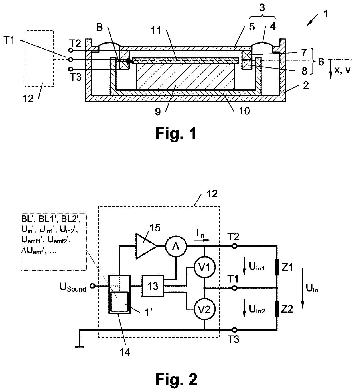
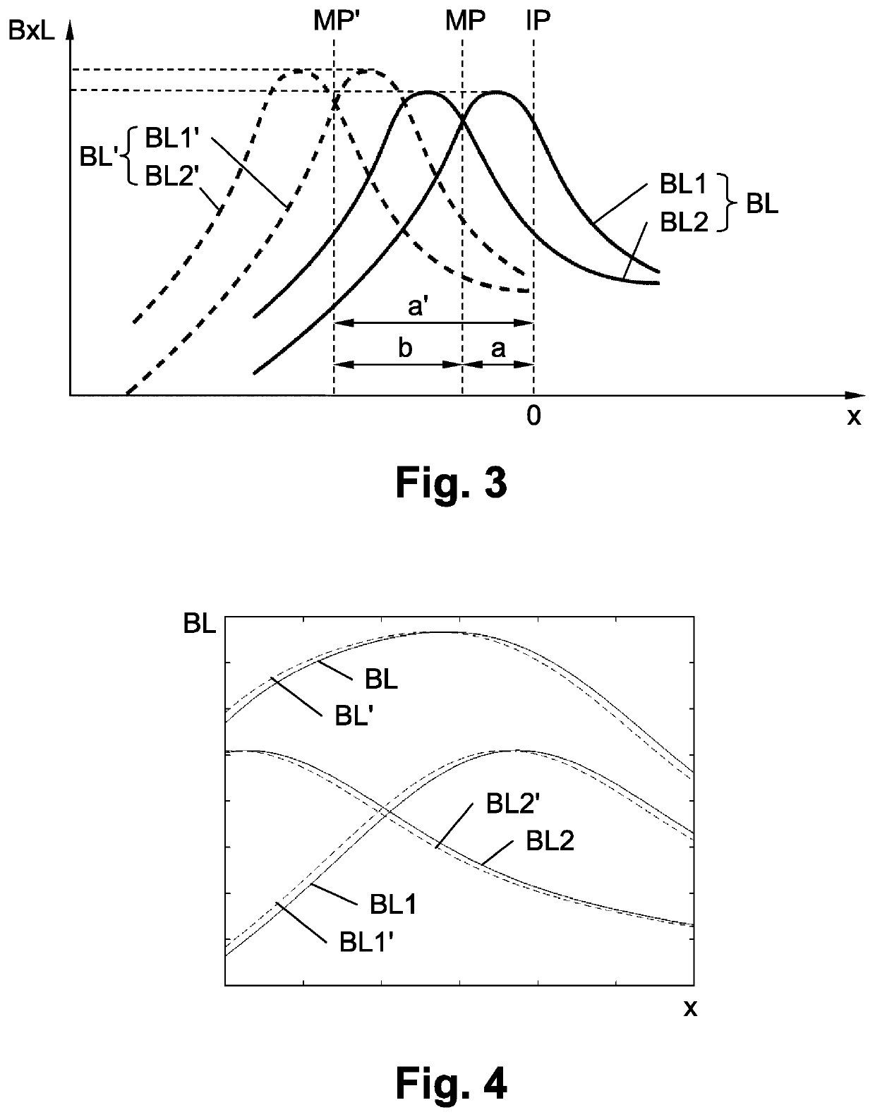
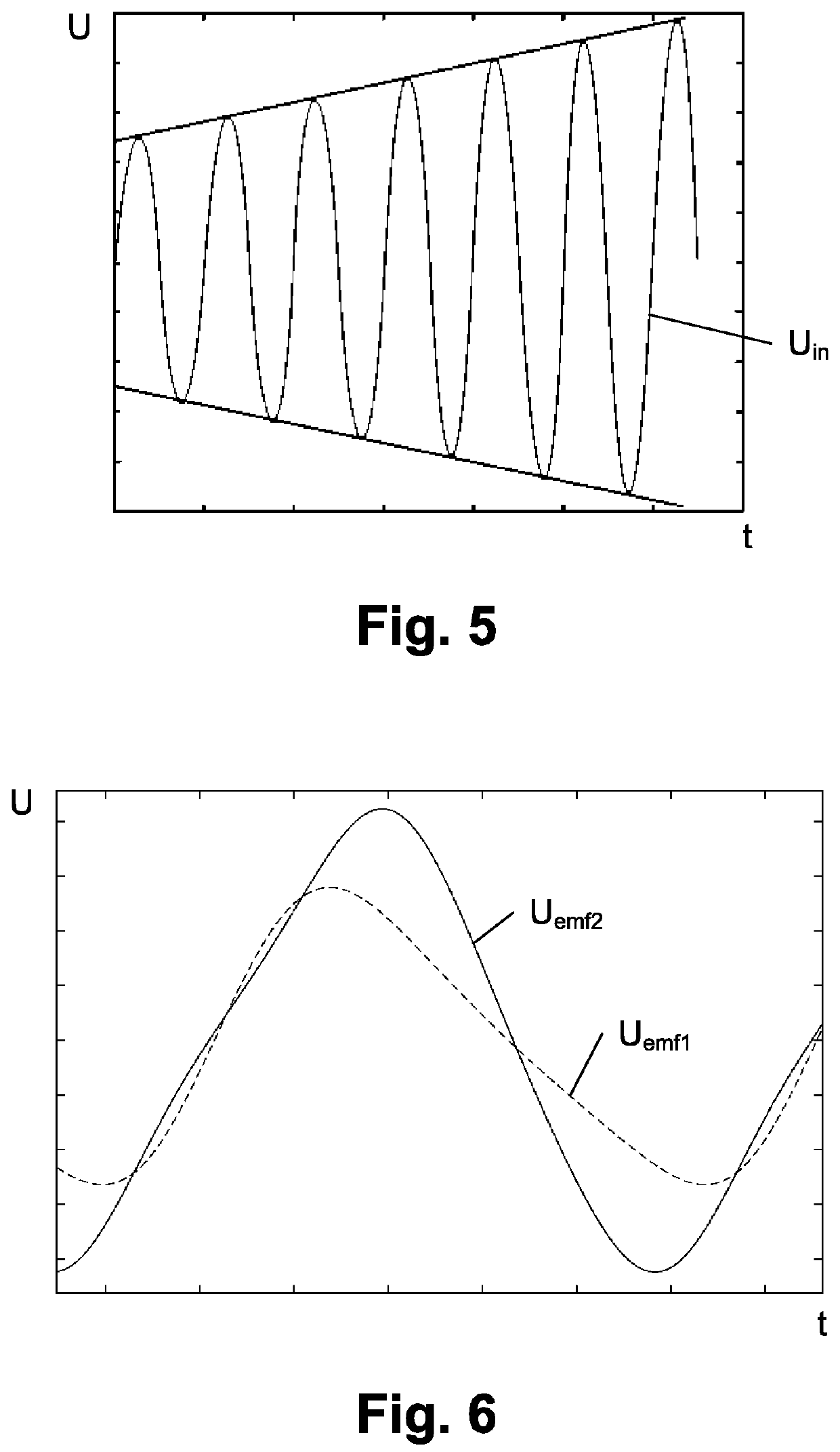
[0124]In a first preferred embodiment, a first input signal Uin, which is a sine signal with a varying magnitude, is applied to the voice coils 7, 8 of the real electrodynamic acoustic transducer 1, and a second input signal Uin′, which is a sine signal with a varying magnitude as well, is applied to (the voice coils of) the model 1′ of the electrodynamic acoustic transducer 1 in a first step a). FIG. 5 shows an example of such a first input signal Uin (and equally of a second input signal Uin′). The magnitude particularly may change linearly over time, in steps or sample by sample. In detail, the input signals Uin, Uin′ should ensure that the excursion x of the membrane 3 reaches or even exceeds the magnetic zero position MP. In other words, the maximum excursion x of the membrane 3 shall correspond to the offset a of the real electrodynamic transducer or even exceed the offset a (see FIG. 3).

[0125]It should be noted that the magnitude change of the input signals Uin, should be suf...

embodiment 2

[0142]In a second embodiment, which is similar to the first embodiment, the scaling factor k is determined in a slightly different way.

[0143]In contrast to the first embodiment, the first input signal U1 applied to the voice coils 7, 8 of the electrodynamic acoustic transducer 1 in step a) is a sine signal with constant magnitude and not a sine signal with a varying magnitude. Nevertheless, the second input signal Uin′ applied to the model 1′ of the electrodynamic acoustic transducer 1 in step a) again is a sine signal with a varying magnitude. Beneficially, the first input signal Uin and the second input signal Uin′ are sinus signals at the resonant frequency of the electrodynamic acoustic transducer 1 again.

[0144]Shifting the modeled driving force function BL′, BL1′, BL2′ in step c) is done in the same way as in the embodiment 1. In particular it should be taken care of that step c) is executed at the same or at least comparable membrane excursions x in the real electrodynamic aco...


PUM


Abstract

Method and electronic circuit for determining a scaling factor k for a driving force function of a model of an electrodynamic acoustic transducer having at least two voice coils. Input signal fed into the transducer and it's model cause electromotive forces. A shift for the driving force function is determined on the base of the ratios between the real electromotive forces and the modeled electromotive forces. Finally, the scaling factor k is determined on the basis of a deviation between the real electromotive forces and the modeled electromotive forces at time points where the real electromotive forces and the modeled electromotive forces each are equal. The invention moreover relates to an electronic circuit for performing the above steps, and to a transducer system with the electronic circuit and a connected transducer.

Description

PRIORITY[0001]This patent application claims priority from Austrian Patent Application No. A50365 / 2019, filed on Apr. 23, 2019, the disclosure of which is incorporated herein, in its entirety, by reference.BACKGROUNDa. Technical Field[0002]The invention relates to a method for improving a driving force function dependent on a membrane excursion of a model of an electrodynamic acoustic transducer. The electrodynamic acoustic transducer comprises a membrane, a coil arrangement with at least two coils attached to the membrane, a magnet system being designed to generate a magnetic field transverse to a longitudinal direction of a wound wire of the coil arrangement and input terminals for receiving an input signal. Moreover, the invention relates to an electronic circuit, comprising a model of an electrodynamic acoustic transducer, in which the above method for improving the driving force function is executed. Finally, the invention relates to a transducer system, comprising an electrody...

Claims


Application Information

Patent Timeline
Patent Type & Authority Applications(United States)
IPC IPC(8): G06F30/367H04R3/08H04R9/04H04R1/24H04R9/18H04R9/02
CPCH04R3/08H04R1/24G06F2119/14G06F2111/10H04R9/18G06F30/367H04R9/025H04R9/04H04R3/00H04R9/02H04R9/06G06F30/373H04R2209/041
Inventor REINING, FRIEDRICH
Owner SOUND SOLUTIONS INTERNATIONAL COMPANY LTD
Why Eureka
Try Eureka