Dynamic range compression method

Active Publication Date: 2020-10-29
ATEME
View PDF0 Cites 2 Cited by
  • Summary
  • Abstract
  • Description
  • Claims
  • Application Information

AI Technical Summary

Benefits of technology

The present patent text describes a method for processing video streams to downgrade them to the standard definition (SDR) format automatically. This method is cost-effective compared to producing an HD / SDR double-feature. The method is especially useful for broadcasting video content in real-time. The method uses a fast and reliable method to estimate the minimum and maximum brightness values of a scene to maintain the fade-type transition effect. Additionally, safety factors are used to ensure the content is not underestimated or overestimated, depending on the type of fade transition.

Problems solved by technology

In addition, not all HDR televisions have the same dynamic range.
Consequently, programs broadcast in HDR are received by televisions which do not necessarily have the necessary rendering capability.
Program broadcasting using high-dynamic-range (HDR) technology is subject to a number of constraints.
Broadcasting programs in real time, using high-dynamic-range (HDR) technology or otherwise, introduces delay and speed problems.
The use of HDR and TMO technologies adds constraints related to video effects (transition effects for example).
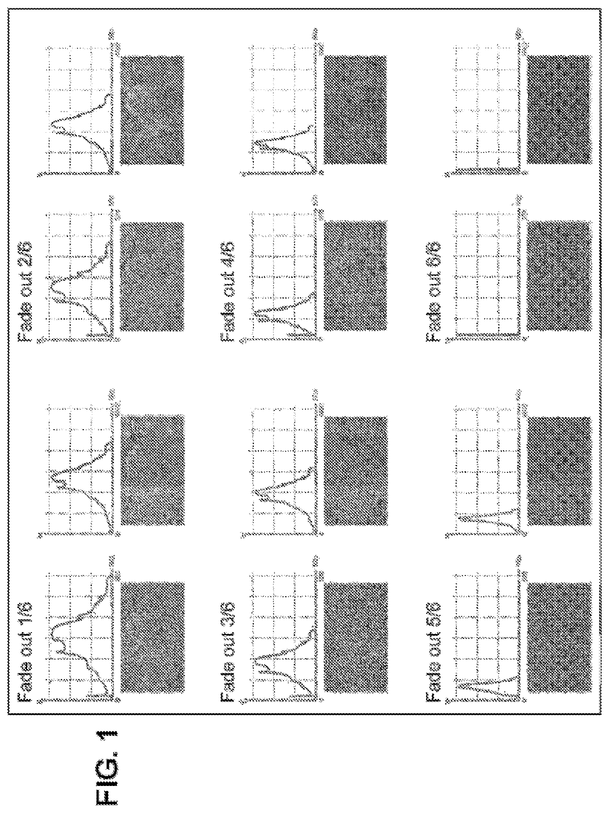
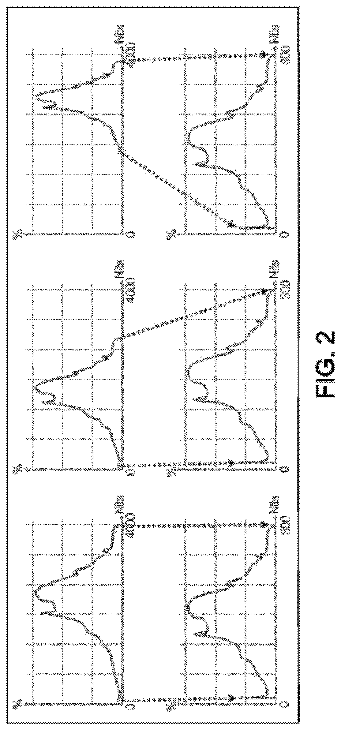
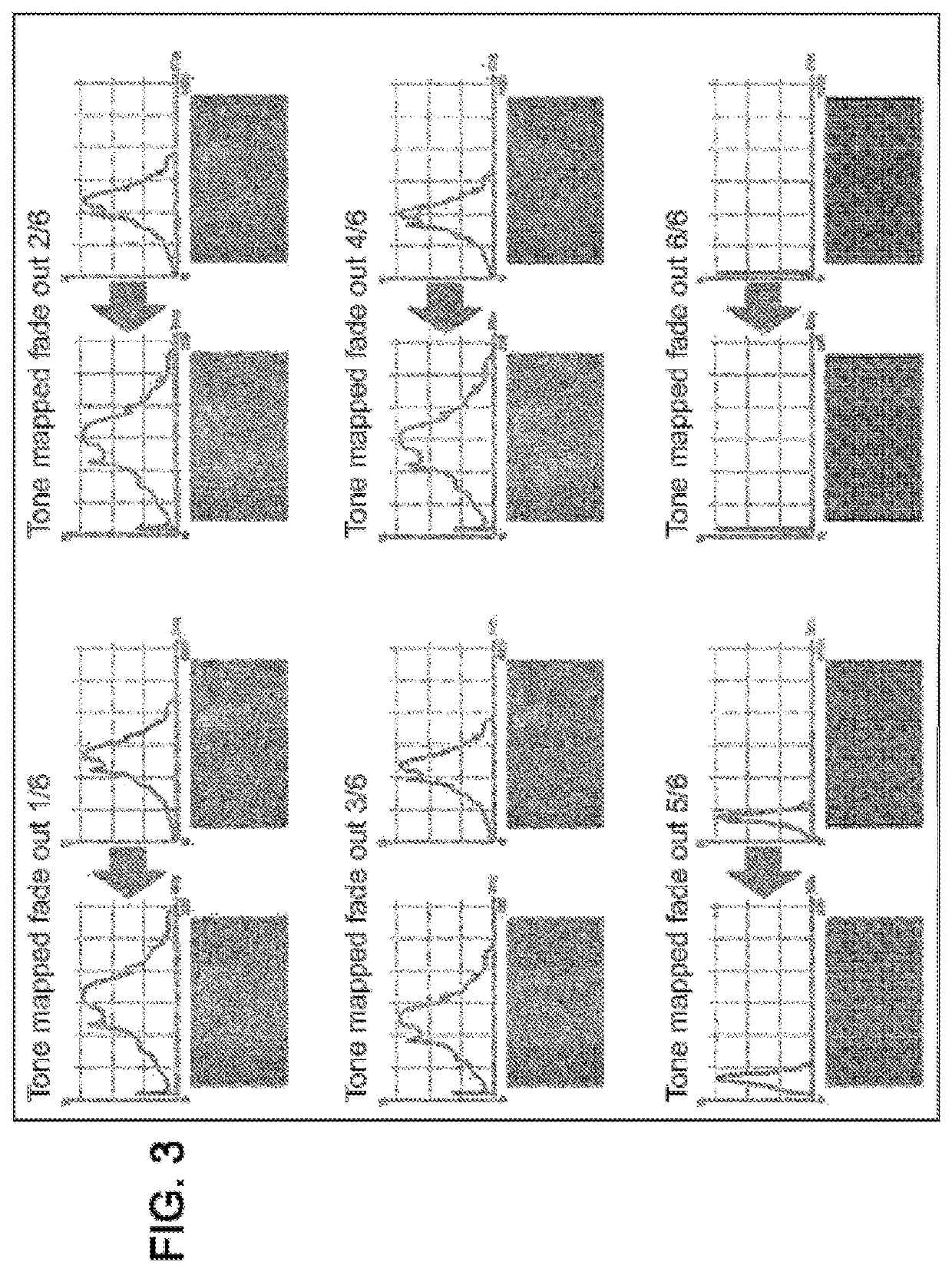
Consequently, the use of a TMO dynamic range compression algorithm alters the rendering of the fade effect in an undesirable manner, regardless of the fade effect (opening / closing fade for example).
This therefore constitutes a problem for producers of video content.
However, the TMO dynamic range compression algorithms proposed by the prior art do not provide for dealing with video effects such as transition effects for example.
Such a method is therefore not suitable for the broadcasting of video content in real time.
Consequently, even in the case that the analysis of the sequence is carried out over a rolling, rather than complete, window, a significant delay results nonetheless.

Method used


Image

  • Dynamic range compression method
  • Dynamic range compression method
  • Dynamic range compression method

Examples


Embodiment Construction

[0058]FIG. 4 illustrates an exemplary implementation of the subject disclosure. A detection module MOD_DETECT 402 detects, from incoming HDR video content “Video HDR live”, a transition effect such as a fade effect for example. The video content “Video HDR live” refers to HDR video content broadcast in real time. In the incoming video content “Video HDR live”, the maximum dynamic range and the dynamic range actually used are defined.

[0059]The detection module MOD_DETECT 402 which represents a transition effect detection module indicates the probability of being in a transition. It operates with N memory frames, where N is a natural integer greater than or equal to two. The detection module MOD_DETECT 402 makes it possible to extract parameters associated with the detected transition effect.

[0060]The parameters associated with the detected transition effect are then transmitted to an SDR dynamic range calculation module represented by MOD_CAL_DYN_SDR 403 in FIG. 4. A transformation c...


PUM


Abstract

Disclosed is a method for processing a video stream including a set of images liable to contain a transition effect, the method including the following steps: detecting a fade-type transition effect within the set of images of the video stream and, where appropriate, calculating minimum and maximum brightnesses LMIN and LMAX for each image of the set of images containing the fade; estimating minimum and maximum brightnesses EMIN and EMAX for all of the images not containing the detected transition effect; determining minimum and maximum brightnesses SMIN and SMAX for a standard dynamic range; calculating minimum and maximum brightnesses TMIN and TMAX depending on the minimum and maximum brightnesses LMIN, LMAX, EMIN, EMAX, SMIN and SMAX calculated and determined beforehand; transmitting the calculated minimum and maximum brightnesses TMIN and TMAX with a view to dynamic range compression.

Description

CROSS-REFERENCE TO RELATED APPLICATIONS[0001]This application claims priority benefit under 35 U.S.C. § 119(d) from French Patent Application No. 17 63357, filed Dec. 29, 2017, the disclosure of which is incorporated by reference herein in its entirety.BACKGROUND OF THE INVENTIONField of the Invention[0002]The present subject disclosure relates to the field of image and video processing, more specifically to the processing of video brightness dynamic range. The subject disclosure relates to a method for processing a video stream containing a transition effect.Description of the Related Art[0003]The audiovisual sector is experiencing substantial growth. Indeed, following the development of high-definition television, ultra-high-definition television has arrived on the market. The gain in perceived quality brought about by the increase in resolution is starting to tail off. Consequently, much work is currently being carried out on video brightness dynamic range. There are two types of...

Claims


Application Information

Patent Timeline
IPC IPC(8): G06T5/00G06T5/50
CPCG06T5/50G06T5/009G06T2207/20008G06T2207/10016G06T2207/20208G06T5/92
Inventor GUIONNET, THOMAS
Owner ATEME
Why Eureka
Try Eureka