Image capturing apparatus and control method thereof, and orientation angle calculation apparatus

Active Publication Date: 2020-10-29
CANON KK
View PDF0 Cites 0 Cited by
  • Summary
  • Abstract
  • Description
  • Claims
  • Application Information

AI Technical Summary

Benefits of technology

[0006]Having been achieved in light of the above-described problem, the present invention provides an image capturing apparatus which can estimate an orientation accurately when estimating

Problems solved by technology

On the other hand, output values from the angular velocity sensor contain error, and thus continuing to integrate the output values from the angular velocity sensor will result in the calculated orientation gradually deviating from the true value.
However, the technique disclosed in Japanese Patent Laid-Open No. 2013-200162 has the following problem.
However, the quaternion cannot be estima

Method used


Image

  • Image capturing apparatus and control method thereof, and orientation angle calculation apparatus
  • Image capturing apparatus and control method thereof, and orientation angle calculation apparatus
  • Image capturing apparatus and control method thereof, and orientation angle calculation apparatus

Examples


Example

First Embodiment

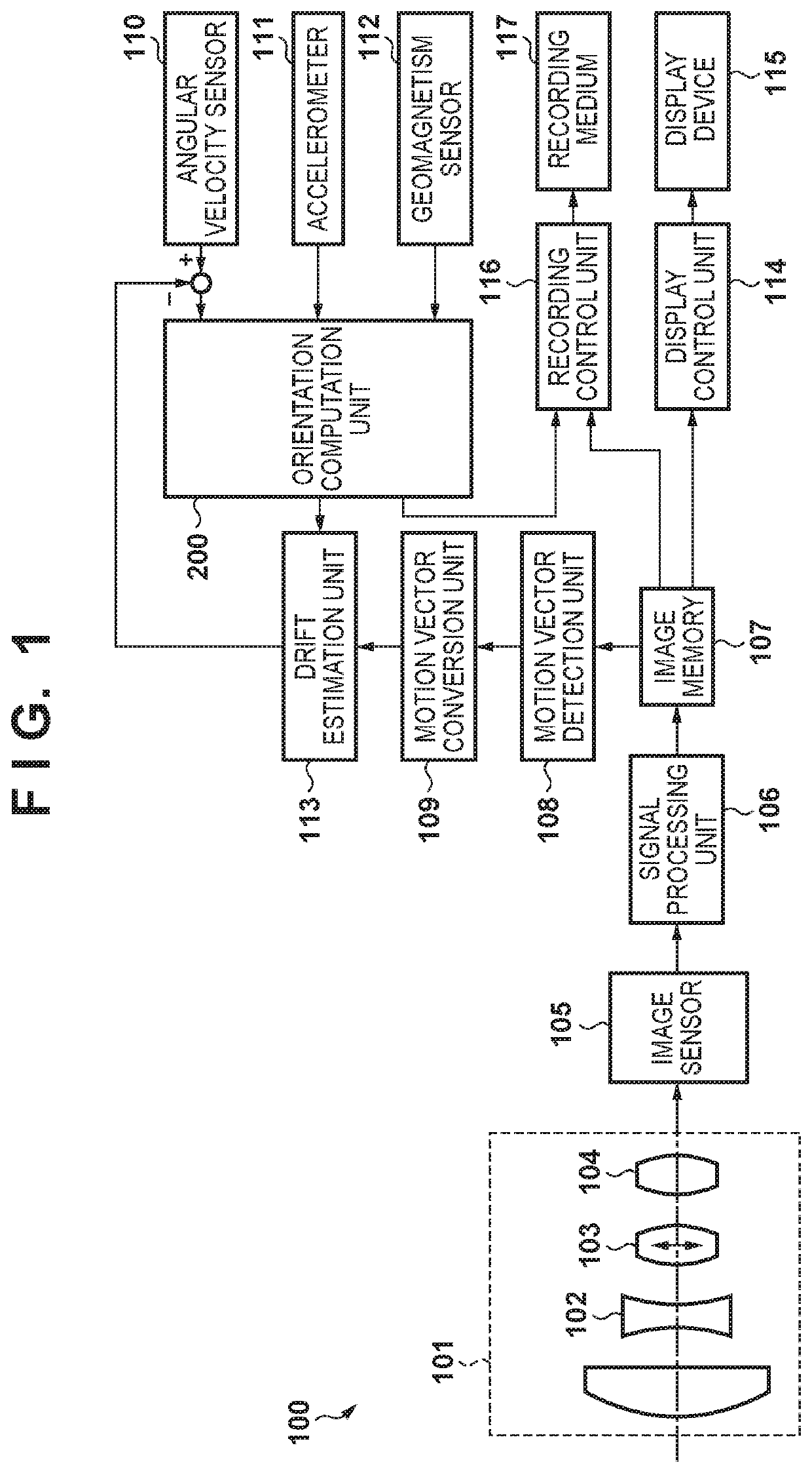
[0022]FIG. 1 is a block diagram illustrating the configuration of an image capturing system 100 according to a first embodiment of the present invention. The image capturing system 100 is an interchangeable-lens or a fixed-lens digital camera used mainly for shooting still images and moving images. However, the scope to which the present invention is applied is not limited to digital cameras, and the present invention can be applied in a variety of other types of image capturing systems as well.

[0023]As illustrated in FIG. 1, the image capturing system 100 is constituted by an interchangeable-lens camera including an interchangeable lens and a camera body, or by a fixed-lens camera, where the interchangeable lens is used by being attached to the camera body.

[0024]An image capturing lens 101 includes a zoom lens 102 which magnifies images, an image stabilization lens 103 such as a shift lens which stabilizes images, and a focus lens 104 which adjusts the focus. Accord...

Example

Second Embodiment

[0077]FIG. 7 is a block diagram illustrating the configuration of an image capturing system 150 according to a second embodiment of the present invention. Note that elements that are the same as those illustrated in FIG. 1 will be given the same reference numerals, and will not be described. Compared to the configuration illustrated in FIG. 1, FIG. 7 removes the drift estimation unit 113, and adds a drift estimation unit 118, which carries out control different from that of the drift estimation unit 113. Furthermore, the orientation computation unit 200 illustrated in FIG. 1 has been replaced with an orientation computation unit 250, which has a different internal configuration. The configuration and operations of the orientation computation unit 250 according to the present embodiment will be described in detail below with reference to the block diagram in FIG. 8. In FIG. 8, elements that are the same as those illustrated in FIG. 4 will be given the same reference ...


PUM


Abstract

An image capturing apparatus comprises an angular velocity detection sensor that detects an angular velocity, an acceleration detection sensor that detects an acceleration, a motion vector detection unit that detects a motion vector on the basis of an image captured by the image capturing apparatus; and a calculation unit that calculates an orientation angle of the image capturing apparatus on the basis of a detection value from the angular velocity detection sensor, a detection value from the acceleration detection sensor, and a detection value from the motion vector detection unit, wherein the calculation unit corrects an output of the angular velocity detection sensor using the detection value obtained by the motion vector detection unit, and calculates an orientation angle of the image capturing apparatus on the basis of the corrected value.

Description

BACKGROUND OF THE INVENTIONField of the Invention[0001]The present invention relates to a technique, used in an image capturing apparatus which requires orientation information, for estimating the orientation of the image capturing apparatus using a plurality of sensors.Description of the Related Art[0002]For some time, methods have been known in which the orientation of a moving object is estimated using a sensor device including an angular velocity sensor, an accelerometer, and a geomagnetism sensor. Relative orientation changes can be calculated from detection results from the angular velocity sensor. The orientation can be estimated by integrating these orientation changes.[0003]On the other hand, output values from the angular velocity sensor contain error, and thus continuing to integrate the output values from the angular velocity sensor will result in the calculated orientation gradually deviating from the true value. A method has therefore been proposed in which the output ...

Claims


Application Information

Patent Timeline
IPC IPC(8): G06T7/70G01C21/08G01P3/00G01P13/00G01P15/08G01C1/00G06T7/223
CPCG01P3/00G06T7/70G01C21/08G01P13/00G01P15/08G06T7/223G01C1/00G06T2207/10016G06T2207/20021G06T7/73G06T2207/30244
Inventor HIRAMA, TOMOHIRO
Owner CANON KK
Why Eureka
Try Eureka