Ripple count circuit including varying ripple threshold detection

a ripple threshold and ripple count technology, applied in the direction of dc motor speed/torque control, counting chain asynchronous pulse counters, control systems, etc., can solve the problems of limited overall performance of the motor, high cost of controllers such as field programmable gate arrays (fpgas),

Active Publication Date: 2020-10-29
INTEVA FRANCE
View PDF1 Cites 4 Cited by
  • Summary
  • Abstract
  • Description
  • Claims
  • Application Information

AI Technical Summary

Benefits of technology

[0004]A motor control system includes a variable voltage supply in signal communication with a direct current (DC) motor. The DC motor includes a rotor induced to rotate in response to a drive current generated by a variable supply voltage delivered by the voltage supply. The rotation of the rotor 103 generates a mechanical force that drives a component. A ripple count circuit 104 is configured to filter the drive cur...

Problems solved by technology

However, these attempts have required the implementation of highly expensive controllers such as Field Programmable Gate Arrays (FPGAs), for example, to execute the computations ...

Method used


Image

  • Ripple count circuit including varying ripple threshold detection
  • Ripple count circuit including varying ripple threshold detection
  • Ripple count circuit including varying ripple threshold detection

Examples


Embodiment Construction

[0018]Conventional DC motor position systems utilizing a HES and a magnetic ring are expensive and complex. In addition, the frequency of the measured flux must be further computed thereby extending the time needed to determine the corresponding rotor speed. Attempts to overcome the disadvantages of the HES and magnetic ring have led to the utilization of highly expensive digital controllers that perform complex algorithms such as a fast Fourier transform, for example, to calculate the rotor speed based on the electrical current driving the DC motor.

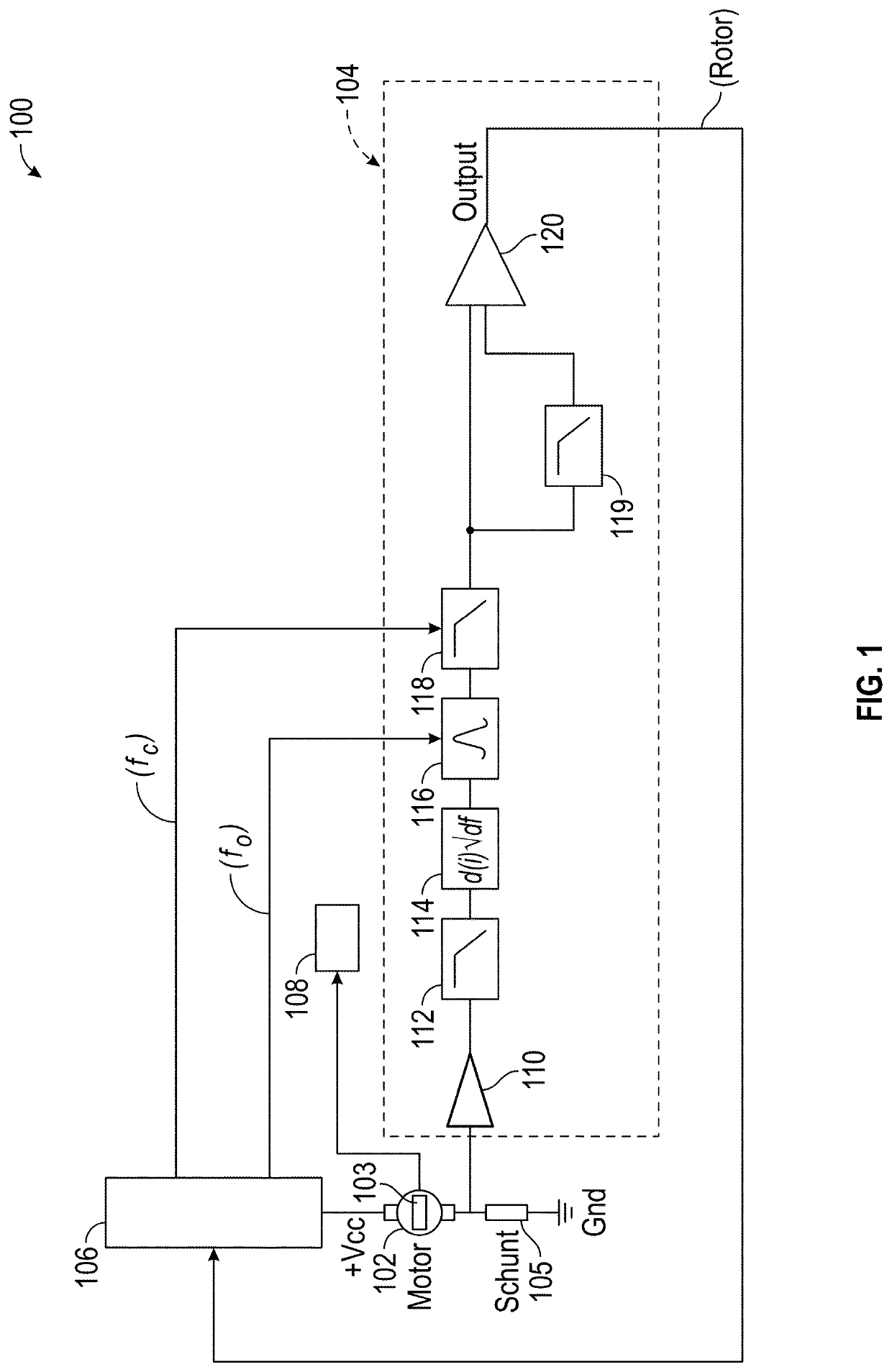
[0019]Various non-limiting embodiments described herein provide a ripple count circuit configured to determine a rotor speed of a DC motor based on a residual ripple current. During operation of the DC motor, a stationary energy unit, sometimes referred to as a stator or field winding, is energized with electrical current. The current flowing through the field winding generates a magnetic field that induces rotation of a rotor, sometimes...


PUM


Abstract

A motor control system includes a variable voltage supply in signal communication with a direct current (DC) motor. The DC motor includes a rotor induced to rotate in response to a drive current generated by a variable supply voltage delivered by the voltage supply. The rotation of the rotor (103) generates a mechanical force that drives a component. A ripple count circuit (104) is configured to filter the drive current based on a rotational speed (ω) of the rotor (103) to generate a filtered drive current signal, and to generate a varying threshold based on the filtered drive current signal. Based on a comparison between the filtered drive current signal and the varying threshold, the ripple count circuit (104) generates a pulsed output signal indicative of the rotational speed (ω) of the rotor and a rotational position (θ) of the rotor.

Description

TECHNICAL FIELD[0001]Exemplary embodiments of the present disclosure are related to direct current (DC) motors, and more particularly, to DC motors for operating electrically operated automotive components.BACKGROUND[0002]Automobile vehicles are increasingly equipped with electrically operated components. For example, vehicles typically include sliding roofs, window glass regulators, or rear view mirrors driven by electric DC motors. Information indicating the rotor speed of the motor can be utilized to determine a position of the component (e.g., the window). Conventional position measurement systems utilize a sensor in conjunction with a magnetic ring to determine the rotor speed of the motor. For example, a Hall Effect Sensor (HES) detects movements of a magnetic ring integrated with the rotor. The magnet ring generates a magnetic flux of varying strength towards the HES depending on the relative axial position of the magnetic ring and sensor. The magnetic flux induces a current,...

Claims


Application Information

Patent Timeline
IPC IPC(8): H02P7/00H03K23/58H02P7/285
CPCH02P7/2855H03K23/58H02P7/0094
Inventor BREYNAERT, FRANÇOISHERPIN, SIMON
Owner INTEVA FRANCE
Why Eureka
Try Eureka