Device for imaging skin

Pending Publication Date: 2020-11-05
KONINKLJIJKE PHILIPS NV
View PDF4 Cites 2 Cited by
  • Summary
  • Abstract
  • Description
  • Claims
  • Application Information

AI Technical Summary

Benefits of technology

[0017]According to the aspects and embodiments described above, the limitations of existing devices are addressed. In particular, according to the above-described aspects and embodiments, images of improved contrast (or resolution) (and thus improved quality) can be acquired. The improved contrast in (or resolution of) the images that is achieved is optimum for features of

Problems solved by technology

As noted above, a limitation with existing devices is that the images acquired by such devices are often not of a high enough contrast (or resolution) for

Method used


Image

  • Device for imaging skin
  • Device for imaging skin
  • Device for imaging skin

Examples


Embodiment Construction

[0026]As noted above, there is provided an improved device for imaging skin, which overcomes existing problems.

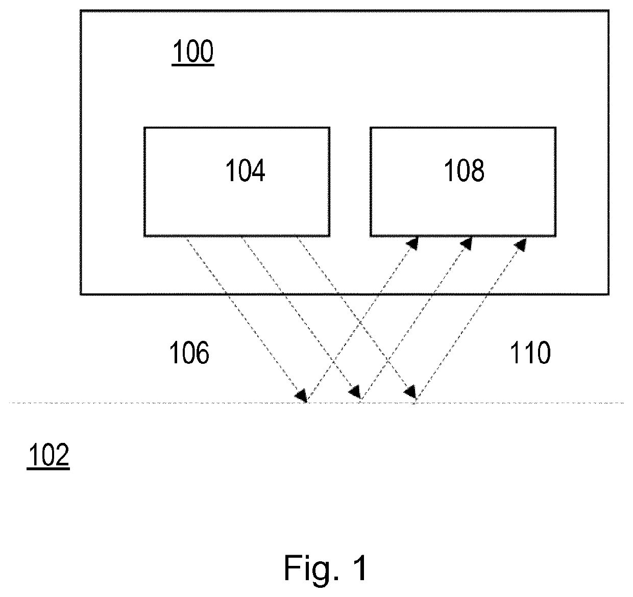
[0027]FIG. 1 illustrates a device 100 for imaging skin 102 according to an embodiment. As illustrated in FIG. 1, the device 100 comprises a light source 104. The light source 104 is configured to emit light 106 to illuminate the skin 102. In some embodiments, the light source 104 can, for example, comprise a semiconductor light source such as a light emitting diode (LED), a resonant cavity light emitting diode (RCLED), a vertical cavity laser diode (VCSELs), an edge emitting laser, or any other semiconductor light source. Alternatively or in addition, in some embodiments, the light source 104 can, for example, comprise an organic light source such as a passive-matrix (PMOLED), an active-matrix (AMOLED), or any other organic light source. Alternatively or in addition, in some embodiments, the light source 104 can, for example, comprise a solid state light source. However, al...


PUM


Abstract

There is provided a device (100) for imaging skin. The device (100) comprises a light source (104) configured to emit light to illuminate the skin (102). The light source (104) has a radiation angle in a range from 5 to 40 degrees. The radiation angle is the angle at which an intensity of the light emitted by the light source (104) is half that of a maximum intensity of the light emitted by the light source (104). The device (100) also comprises an imaging sensor (108) configured to detect light reflected from the skin (102) and convert the detected light into an image of the skin (102).

Description

FIELD OF THE INVENTION[0001]The invention relates to a device for imaging skin, a method of operating the device to image skin and a system for measuring skin texture.BACKGROUND OF THE INVENTION[0002]In the skincare field, it is valuable to acquire images of the skin. For example, images of the skin can be useful for monitoring the state of the skin (such as any deterioration or improvement in the state of the skin) and to detect any skin conditions.[0003]Some existing devices for imaging skin comprise a light source for illuminating the skin while an image is acquired by an imaging sensor of the device. JP 2013 / 026846 discloses an example of a skin observation device where light is applied to the skin. This skin observation device uses a different angle of incidence of light with respect to the optical axis for observing skin texture to that used for observing skin spots.[0004]However, while there exist such devices for imaging skin, the existing devices can suffer from poor image ...

Claims


Application Information

Patent Timeline
IPC IPC(8): A61B5/00
CPCA61B2560/0462A61B5/442A61B5/0077A61B2562/046A61B5/0022A61B5/0002A61B5/0059A61B5/0082
Inventor RAS, ARNOLDUS JOHANNES MARTINUS JOZEPHHERMANS, WALTERVARGHESE, BABU
Owner KONINKLJIJKE PHILIPS NV
Why Eureka
Try Eureka