
Locking Unit and Method

a technology of locking unit and locking mechanism, which is applied in the direction of gearing control, braking system, belt/chain/gearring, etc., can solve the problem of reducing the mass of the entire locking uni

Inactive Publication Date: 2020-11-05
SVM SCHULTZ VERW
View PDF0 Cites 0 Cited by
  • Summary
  • Abstract
  • Description
  • Claims
  • Application Information

AI Technical Summary

Benefits of technology

The patent is about a new design for a fluid-tight embodiment that prevents leakage between parts. This prevents fluid from escaping and causing problems with the movement of an important part called the piston. The design also allows for the piston to be guided only on the center section, which means it doesn't have to support the piston. This allows the housing to be made from a lighter material like plastic, which makes it easier to manufacture.

Problems solved by technology

Such leakage could lead, for example, to pressurized fluid escaping into a space in which it could prevent the movement of the piston.
The proposal is also not only limited here to the more favorable manner of production, but in turn reduces the mass of the entire locking unit since a lighter material is used for the housing.
However, this is not the sole application of the proposed locking unit.

Method used


Image

  • Locking Unit and Method
  • Locking Unit and Method
  • Locking Unit and Method

Examples


second example embodiment

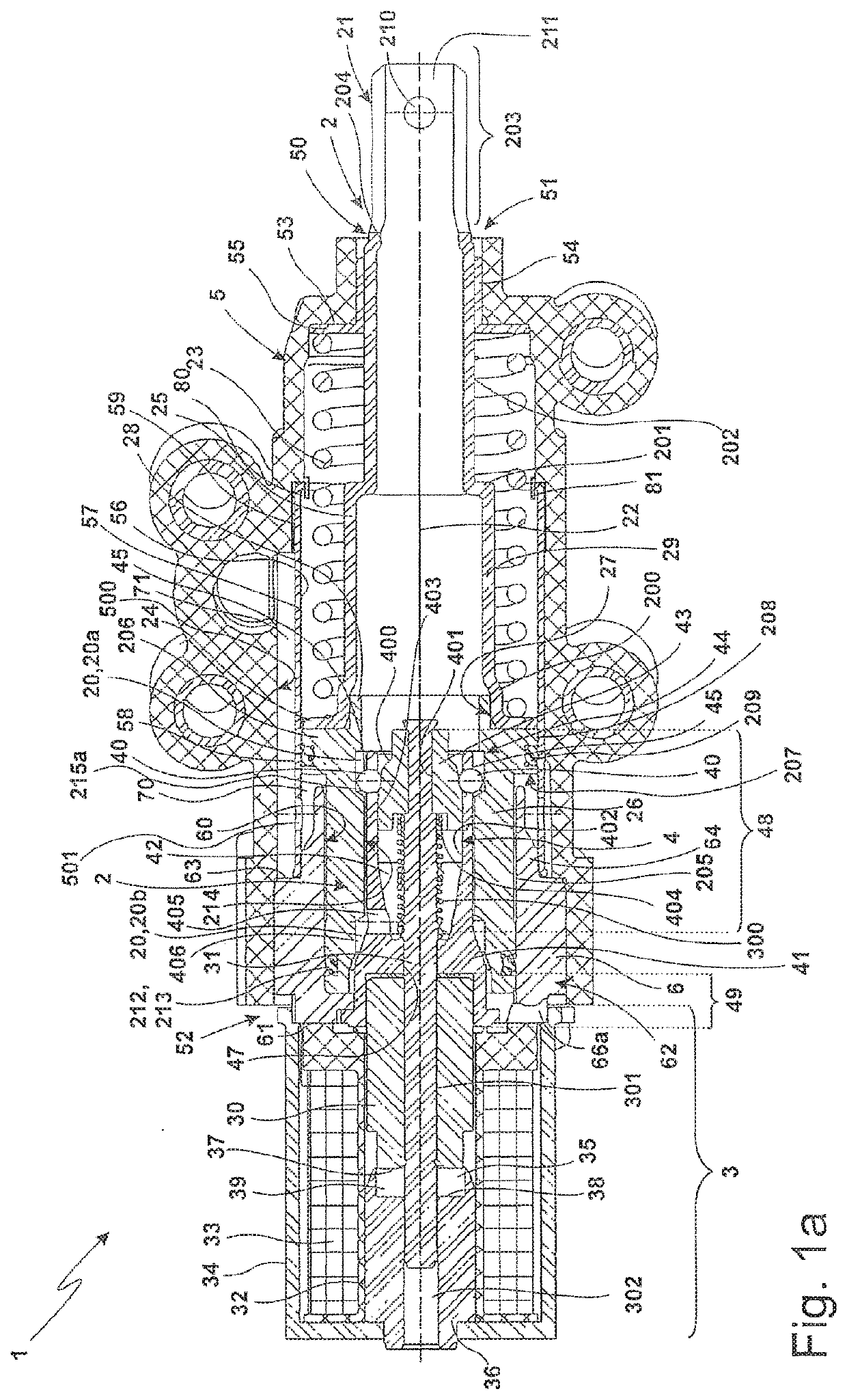
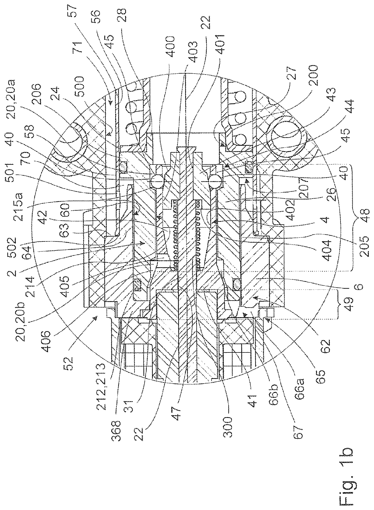
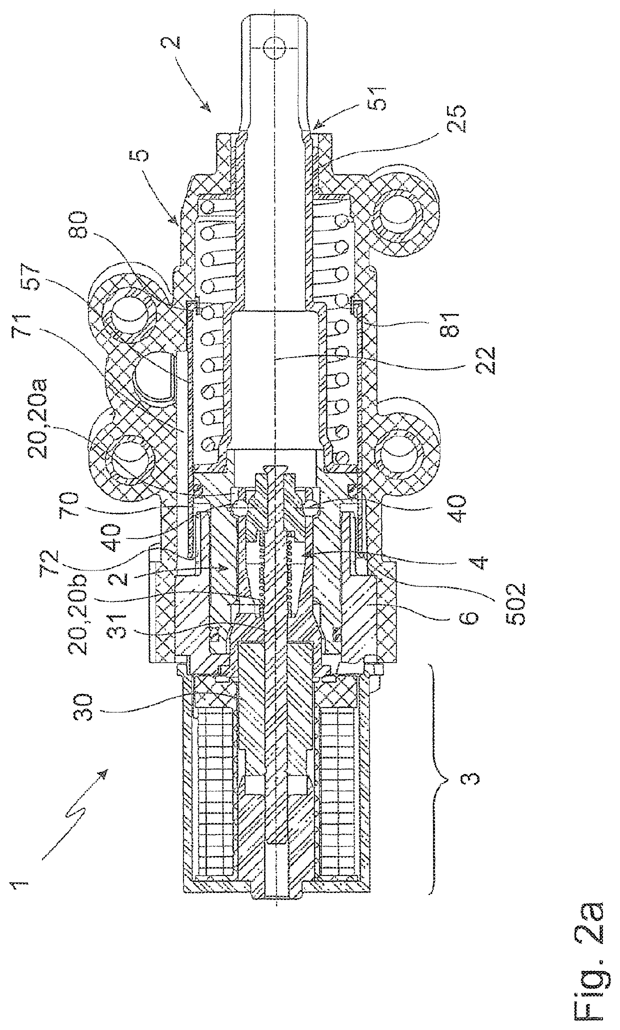
[0162]FIGS. 2a and 2b each show, in a vertical section, the locking unit 1 according to the disclosure in two different positions of the piston.

[0163]In FIG. 2a, the piston 2 is completely retracted in the locking unit 1 and is secured in said end position by the latching unit 4. The completely retracted position of the piston 2 results from the fact that the piston thrust piece 26 is exposed only to a small pressure, if any pressure, which generates a force which is smaller than the opposite spring force of the piston spring 23. In FIG. 2b, the piston 2 is completely pushed out of the locking unit 1 and is likewise secured in said end position by the latching unit 4.

[0164]As already explained, the blocking position of the latching unit 4 is realized in the dropped, i.e., non-energized, state of the solenoid 3, but without the disclosure being set thereto; the blocking position can alternatively also be realized in the energized state of the solenoid.

[0165]In order, for example, now...


PUM


Abstract

The disclosure relates to a locking unit, in particular for the parking lock of an automatic transmission. The locking unit has a solenoid and at least one latching element. The latching element interacts with the armature or the armature rod of the solenoid, and the piston has at least one latching receptacle. The piston is securable by the retaining interaction of the latching element with the latching receptacle. Here, the piston is at least partially mounted in a housing, and the locking unit has an internal tube section, which is connected to the housing in a fluid-tight manner. The disclosure furthermore relates to a method for producing such a locking unit.

Description

CROSS-REFERENCE TO RELATED APPLICATION[0001]This application claims the benefit of German Patent Application No. 10 2019 111 240.0, filed Apr. 30, 2019.INTRODUCTION[0002]The disclosure relates to a locking unit, in particular for the parking lock of an automatic transmission, for locking the movement of a piston which is movable by a drive and in particular can be acted upon with pressure or hydraulic pressure, the locking unit having a solenoid and at least one latching element, and the latching element interacting with the armature or the armature rod of the solenoid, and the piston having at least one latching receptacle, and the piston being securable by the retaining interaction of the latching element with the latching receptacle. The disclosure furthermore relates to a method for producing a locking unit.[0003]A locking unit of the type in question is disclosed, for example, from the applicant's international patent application WO 2013 / 131926.SUMMARY[0004]It is an object of t...

Claims


Application Information

Patent Timeline
Patent Type & Authority Applications(United States)
IPC IPC(8): F16H63/34F16D63/00B60T1/00
CPCB60T1/00F16H63/3475F16D63/006F16H63/3483F16H63/3491F16H63/3433
Inventor HÖLZLE, FLORIANKÄCHLER, MARTINNEGELE, MARCO
Owner SVM SCHULTZ VERW
Features
  • Generate Ideas
  • Intellectual Property
  • Life Sciences
  • Materials
  • Tech Scout
  • Unparalleled Data Quality
  • Higher Quality Content
  • 60% Fewer Hallucinations
Learn More