
Conformable hmd with dynamically adjustable nested ribbon

a dynamically adjustable, nested ribbon technology, applied in the direction of optics, instruments, optics, etc., can solve the problems of inconvenient use, unfavorable use, and heavy front load of hmd, and achieve the effect of increasing the overall flexibility and conformability of the arm

Active Publication Date: 2020-11-12
MICROSOFT TECH LICENSING LLC
View PDF0 Cites 3 Cited by
  • Summary
  • Abstract
  • Description
  • Claims
  • Application Information

AI Technical Summary

Benefits of technology

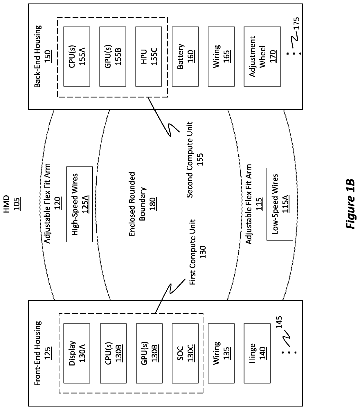
The patent text describes an enclosed head-mounted display (HMD) that includes a front-end housing and a back-end housing, as well as adjustable flex fit arms that connect the front and back housings. The HMD also includes a nested flexible cable ribbon that electrically couples the compute units and includes a dynamic bend that allows for effective expansion or contraction in length as the enclosed rounded boundary changes. The HMD also includes multiple adjustment snaps that allow for independent movement of different parts of the arms, improving flexibility and conformability. The technical effects of this invention include improved fit and comfort, better performance, and more immersive experiences for users wearing the HMD.

Problems solved by technology

Typically, these all-in-one systems include a substantial number of compute units in the front portion / area of the HMD, thereby causing the HMD to be very front heavy and uncomfortable for the user.
In some cases, this rear section can even be coupled to the rear end of the HMD through a large (and typically unsightly) bundled cable that extends from the front of the HMD to the rear of the HMD.
Unfortunately, traditional methods of performing this split have come with many undesired drawbacks and consequences as well.
For instance, with a split architecture, the user either has to place a compute unit somewhere else on his / her body (this can be bothersome in its own accord) or the user's HMD will have large and unsightly cables running the length of the HMD.
Traditional techniques, therefore, have not been optimal for users.

Method used


Image

  • Conformable hmd with dynamically adjustable nested ribbon
  • Conformable hmd with dynamically adjustable nested ribbon
  • Conformable hmd with dynamically adjustable nested ribbon

Examples


Embodiment Construction

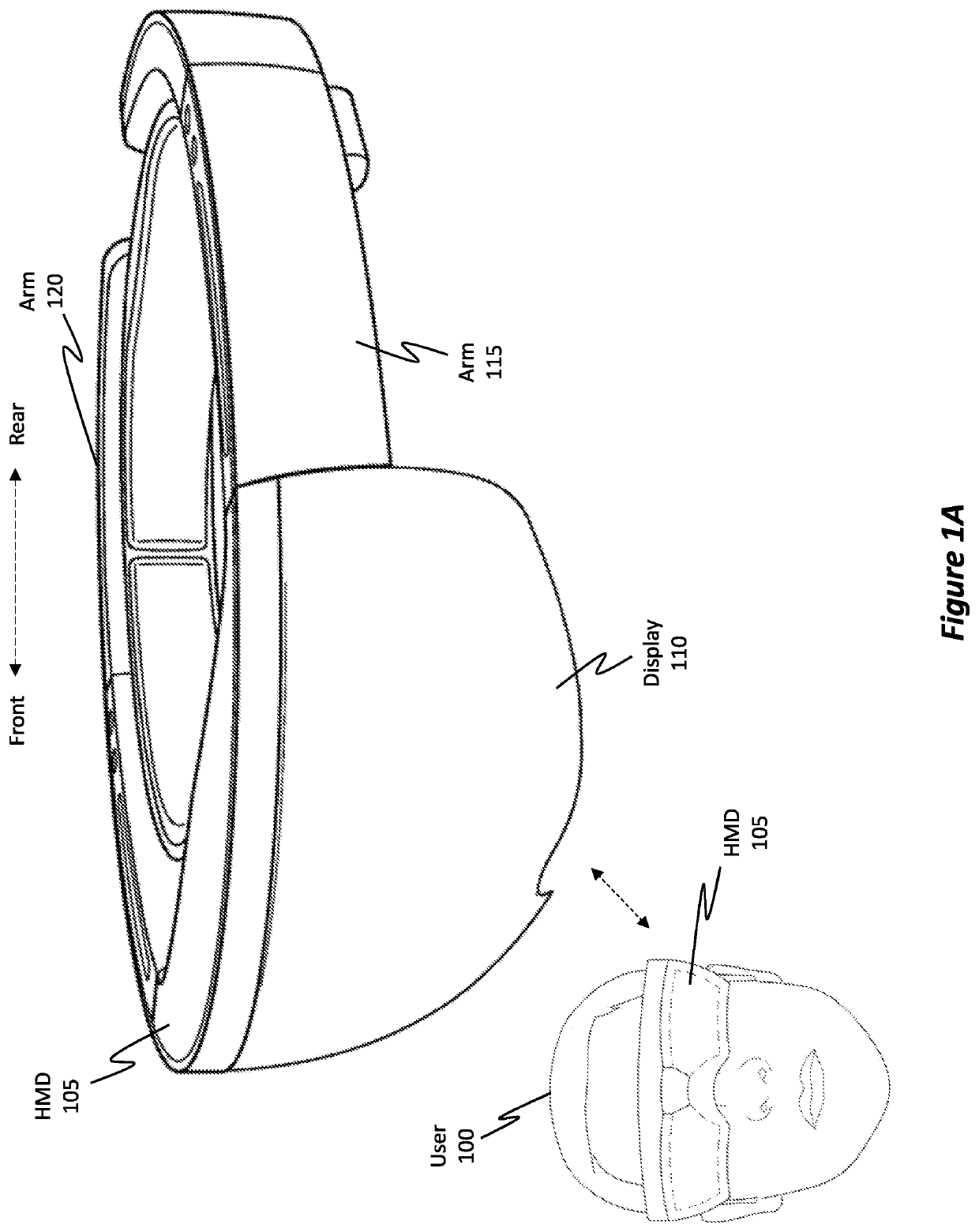
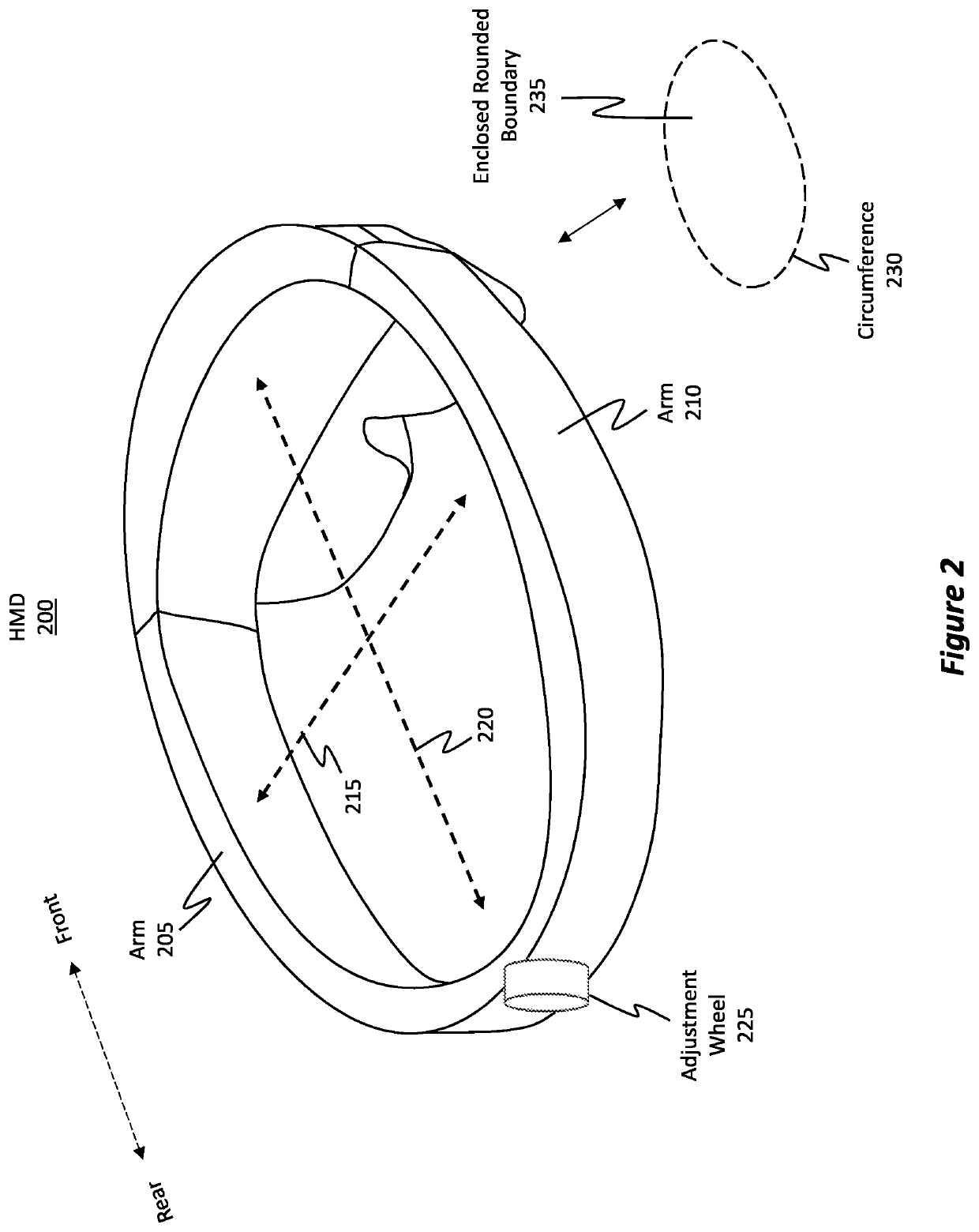
[0029]Embodiments disclosed herein relate to wearable head-mounted devices (HMD) whose circumference is dynamically adjustable to conform to different head sizes and head shapes. The HMD is also specially designed to improve functionality and aesthetics.

[0030]In some embodiments, the HMD includes a front-end and back-end housing, both of which include corresponding compute units. The HMD also includes two adjustable flex fit arms connecting the front-end housing to the back-end housing. Together, these structures define an enclosed rounded boundary that is placeable around a head of a user. The HMD also includes a nested flexible cable ribbon nested within a cavity extending along a length of either the first or second adjustable flex fit arm. The ribbon electrically couples the front and rear compute units and includes a static bend and a dynamic bend. The dynamic bend enables the nested flexible cable ribbon to effectively expand or contract in length (without stretching the ribbo...


PUM


Abstract

A head-mounted device (HMD) whose circumference is dynamically adjustable to conform to different head sizes and shapes is disclosed herein. The HMD includes a front-end and back-end housing. The front-end housing includes a first compute unit, and the back-end housing includes a second compute unit. The HMD also includes two adjustable flex fit arms that connect the front-end housing to the back-end housing. The HMD has an enclosed rounded boundary that is placeable around a user's head. The HMD also includes a nested flexible cable ribbon, which is nested within a cavity of one of the arms and which includes both a static bend and a dynamic bend. The bend radius for the dynamic bend is larger than the bend radius of the static bend. The dynamic bend enables the nested flexible cable ribbon to expand or contract when the circumference of the enclosed rounded boundary changes.

Description

BACKGROUND[0001]Mixed-reality (MR) systems / devices include virtual-reality (VR) and augmented-reality (AR) systems. Conventional VR systems create completely immersive experiences by restricting users' views to only virtual images rendered in VR scenes / environments. Conventional AR systems create AR experiences by visually presenting virtual images that are placed in or that interact with the real world. As used herein, VR and AR systems are described and referenced interchangeably via use of the phrase “MR system.” A head-mounted device (HMD) provides the display used by the user to view and / or interact with virtual images provided within an MR scene.[0002]Currently, there are some “all-in-one” MR head-mounted systems. These systems are all-in-one because they do not physically attach to an external computer; rather, the HMD includes substantially all of the compute units necessary to provide an MR scene to a user, or the HMD at least includes adequate networking components to obta...

Claims


Application Information

Patent Timeline
Patent Type & Authority Applications(United States)
IPC IPC(8): G02B27/01
CPCG02B2027/0169G02B2027/0154G02B27/0176G02B2027/0152G02B2027/0161
Inventor WILLIAMS, JASON PAULBOSWELL, TREVOR GRANTALDANA, LEONARDO
Owner MICROSOFT TECH LICENSING LLC
Learn More