Flexible and comformable embolic filtering devices

a filtering device and flexible technology, applied in the field can solve the problems of affecting the patient's health, affecting the patient's life, and releasing emboli into the circulatory system can be extremely dangerous and sometimes fatal, and achieves enhanced flexibility and bendability of embolic filtering devices, high flexibility and conformability, and high flexibility

Inactive Publication Date: 2007-10-25
ABBOTT CARDIOVASCULAR
View PDF4 Cites 17 Cited by
  • Summary
  • Abstract
  • Description
  • Claims
  • Application Information

AI Technical Summary

Benefits of technology

[0014] The present invention provides a highly flexible cage (also referred to as a “basket”) for use with an embolic filtering device designed to capture embolic debris created during the performance of a therapeutic interventional procedure, such as a balloon angioplasty or stenting procedure, in a body vessel. The present invention provides the physician with an embolic filtering device having high flexibility to be steered through tortuous anatomy, but yet possessing sufficient strength to hold open a filtering element against the wall of the body vessel for capturing embolic debris. An embolic filtering device made in accordance with the present invention is relatively easy to deploy, has good visibility under fluoroscopy, and has good flexibility and is conformable to the patient's anatomy.
[0017] In one aspect of the present invention, the enhanced flexibility and bendability of the embolic filtering device is achieved through the utilization of a unique cage design having a highly flexible and conformable circumferential member which is adapted to expand and conform to the size and shape of the body vessel. The expandable cage further includes at least one proximal strut having an end connected to a guide wire and the other end attached to the circumferential member. At least one distal strut is attached to the circumferential member and has its other end attached to the guide wire. The filter element is attached to the circumferential member and will open and close as the expandable cage moves between its expanded, deployed position and its unexpanded, delivery position. The circumferential member is self-expanding and is made from a highly flexible material which allows it to conform to the particular size and shape of the body vessel. This high flexibility and conformability of the circumferential member allows it to deployed in curved sections of the patient's anatomy and other eccentric vessel locations having non-circular shaped lumens. This allows an embolic filtering device made in accordance with the present invention to be deployed in locations in the patient's anatomy which might not be otherwise suitable for stiffer filtering devices. Moreover, due to the high flexibility and conformability of the circumferential member, an embolic filtering device made in accordance with present invention is less likely to create gaps between the filtering element and the wall of the vessel once deployed in the lumen. Therefore, the potential release of embolic debris past the deployed filter can be reduced.
[0018] In another aspect of the present invention, bending regions formed on the circumferential member help to actuate the circumferential member between its unexpanded and expanded positions. In one aspect of the present invention, these bending regions are substantially U-shaped bends formed on the circumferential member at various locations along the member. While the circumferential member itself is self-expanding and capable of moving between these positions, the bending regions further enhance the actuation of the circumferential member between these positions. In one particular aspect of the present invention, the proximal strut is attached directly to this bending region. Likewise, a distal strut can be attached to a second bend section. In this fashion, a highly bendable and conformable cage can be produced which should conform to the particular shape of the body vessel once deployed.

Problems solved by technology

However, there is one common problem which can become associated with all of these non-surgical procedures, namely, the potential release of embolic debris into the bloodstream that can occlude distal vasculature and cause significant health problems to the patient.
Additionally, while complete vaporization of plaque is the intended goal during laser angioplasty, sometimes particles are not fully vaporized and enter the bloodstream.
When any of the above-described procedures are performed in the carotid arteries, the release of emboli into the circulatory system can be extremely dangerous and sometimes fatal to the patient.
Debris carried by the bloodstream to distal vessels of the brain can cause cerebral vessels to occlude, resulting in a stroke, and in some cases, death.
Therefore, although cerebral percutaneous transluminal angioplasty has been performed in the past, the number of procedures performed has been somewhat limited due to the justifiable fear of an embolic stroke occurring should embolic debris enter the bloodstream and block vital downstream blood passages.
However, it is often difficult to control the size of the fragments which are formed, and the potential risk of vessel occlusion still exists, making such a procedure in the carotid arteries a high-risk proposition.
However, as mentioned above, there can be complications associated with such systems if the vacuum catheter does not remove all of the embolic material from the bloodstream.
Also, a powerful suction could cause trauma to the patient's vasculature.
While a filter can be effective in capturing embolic material, the filter still needs to be collapsed and removed from the vessel.
During this step, there is a possibility that trapped embolic debris can backflow through the inlet opening of the filter and enter the bloodstream as the filtering system is being collapsed and removed from the patient.
Also, while it is beneficial if the area of treatment is located in a substantially straight portion of the patient's vasculature, sometimes the area of treatment is at a curved portion of the body vessel which can be problematic to the physician when implanting the expandable filter.
If the expandable filter portion is too stiff, it is possible that the filter may not fully deploy within the curved portion of the body vessel.
As a result, gaps between the filter and vessel wall can be formed which may permit some embolic debris to pass therethrough.
However, the use of thin material often can reduce the radiopacity of the expandable filter, often making it difficult for the physician to see the filter under fluoroscopy during deployment.
Conversely, the use of thicker materials, which can promote radiopacity of the expandable filter, usually reduces its flexibility, which may impair the deliverability of the expandable filter within the patient.

Method used


Image

  • Flexible and comformable embolic filtering devices
  • Flexible and comformable embolic filtering devices
  • Flexible and comformable embolic filtering devices

Examples


Embodiment Construction

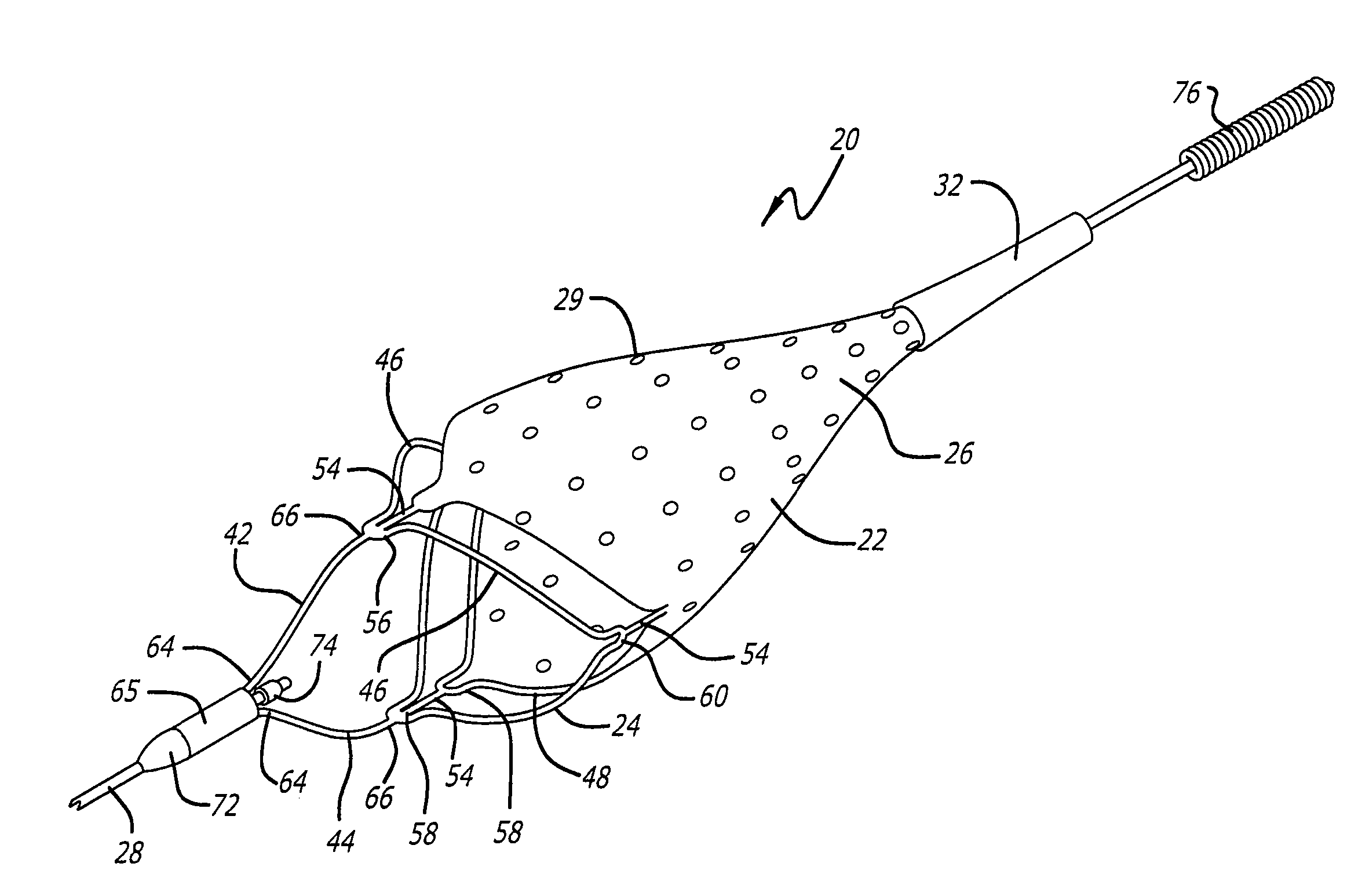
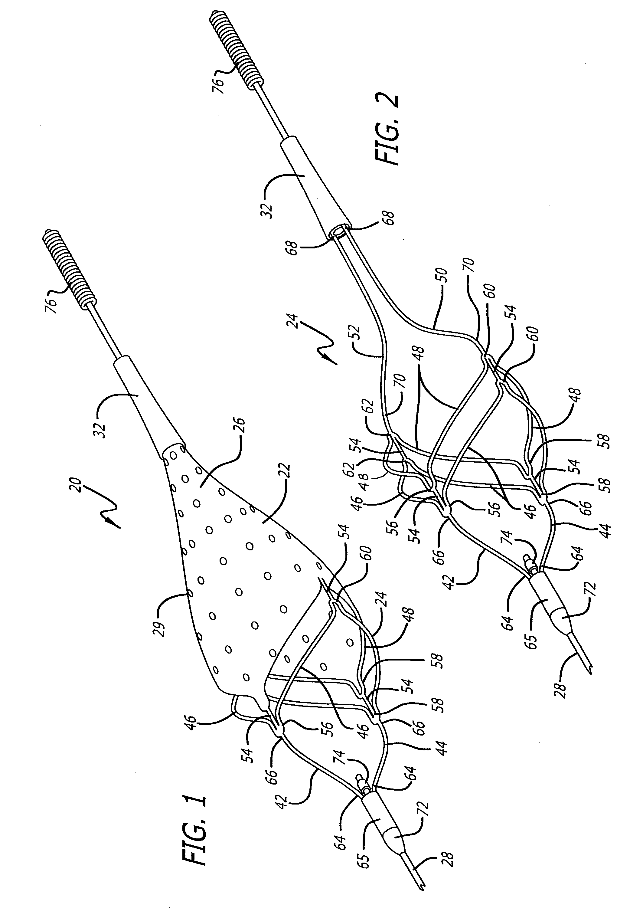
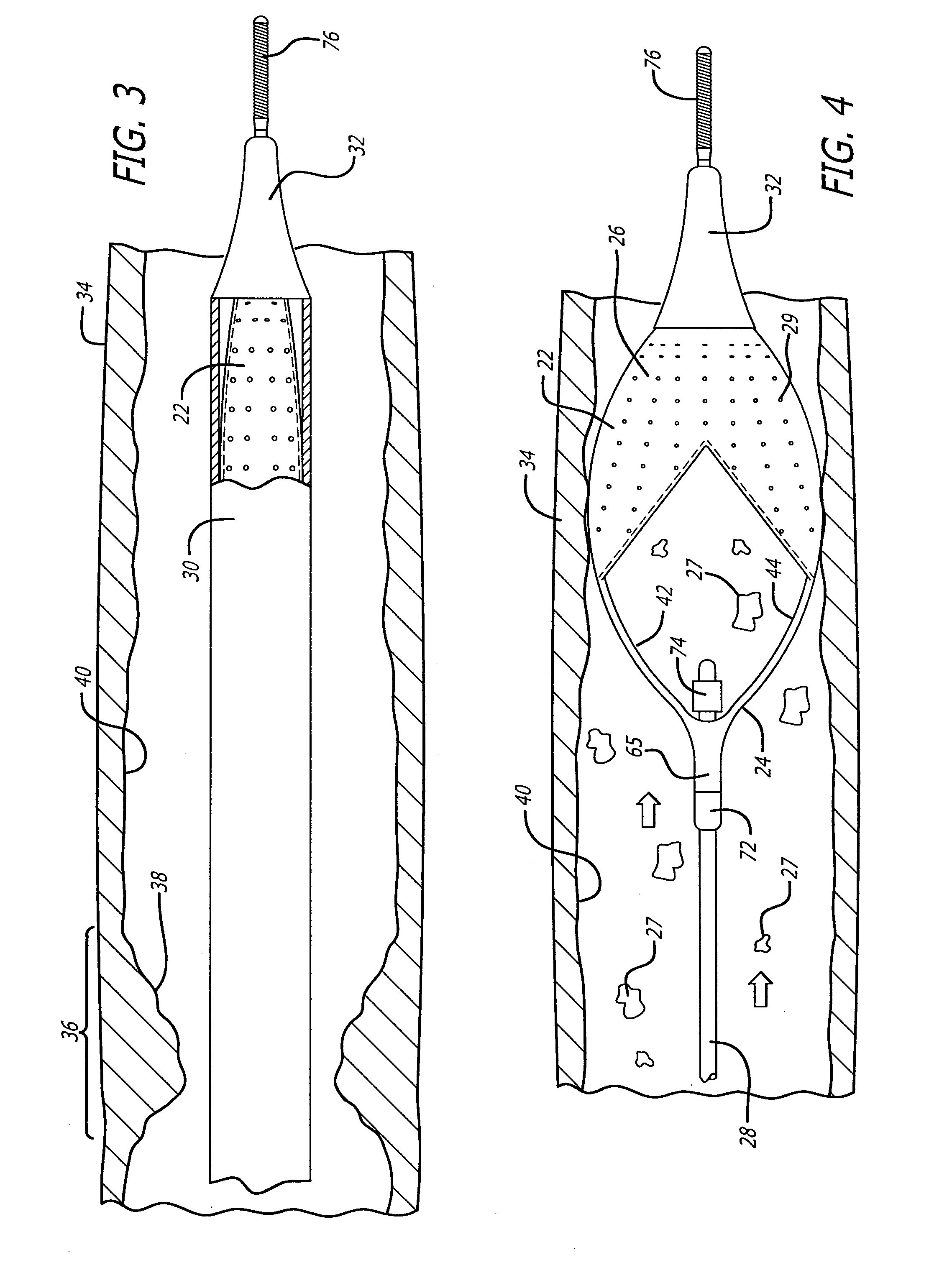
[0033] Turning now to the drawings, in which like reference numerals represent like or corresponding elements in the drawings, FIGS. 1 and 2 illustrate one particular embodiment of an embolic filtering device 20 incorporating features of the present invention. This embolic filtering device 20 is designed to capture embolic debris which may be created and released into a body vessel during an interventional procedure. The embolic filtering device 20 includes an expandable filter assembly 22 having a self-expanding basket or cage 24 and a filter element 26 attached thereto. In this particular embodiment, the expandable filter assembly 22 is rotatably mounted on the distal end of an elongated (solid or hollow) cylindrical tubular shaft, such as a guide wire 28. The guide wire has a proximal end (not shown) which extends outside the patient and is manipulated by the physician to deliver the filter assembly into the target area in the patient's vasculature. A restraining or delivery shea...


PUM


Abstract

A self-expanding cage for use in conjunction with an embolic filtering device includes one or more circumferential members adapted to expand from an unexpanded position to a expanded position within the patient's body vessel. At least one proximal strut and at least one distal strut are attached to the circumferential member to form the basket. The circumferential member may include a plurality of bending regions which enhance the ability of the circumferential member to move between the unexpanded and expanded positions. The proximal and distal struts can be attached to one of the bending regions. When two or more circumferential members are utilized, each member may be connected by a connecting strut which may be connected at a bending region. The connecting strut can be a straight segment or may have a non-linear shape to provide additional flexibility. The expandable cage can be mounted to a elongated member, such as a guide wire, and can be either permanently mounted or rotatably mounted thereto.

Description

FIELD OF THE INVENTION [0001] The present invention relates generally to filtering devices used when an interventional procedure is being performed in a stenosed or occluded region of a body vessel to capture embolic material that may be created and released into the vessel during the procedure. The present invention is more particularly directed to an embolic filtering device made with an expandable cage possessing good flexibility and bendability, which allows the embolic filtering device to be readily deployed in a bend in a body lumen of a patient. BACKGROUND OF THE INVENTION [0002] Numerous procedures have been developed for treating occluded blood vessels to allow blood to flow without obstruction. Such procedures usually involve the percutaneous introduction of an interventional device into the lumen of the artery, usually by a catheter. One widely known and medically accepted procedure is balloon angioplasty in which an inflatable balloon is introduced within the stenosed re...

Claims


Application Information

Patent Timeline
Patent Type & Authority Applications(United States)
IPC IPC(8): A61M29/00A61F2/01
CPCA61F2/013A61F2230/008A61F2230/0008A61F2230/0006A61F2002/018A61F2/0108
Inventor BOYLE, WILLIAM J.HUTER, BENJAMIN C.HUTER, SCOTT J.PAPP, JOHN E.
Owner ABBOTT CARDIOVASCULAR
Why Eureka
Try Eureka