Eureka AIR delivers breakthrough ideas for toughest innovation challenges, trusted by R&D personnel around the world.

Electrical connector and a control valve including the same

Active Publication Date: 2020-11-12
BORG WARNER INC
View PDF0 Cites 0 Cited by
  • Summary
  • Abstract
  • Description
  • Claims
  • Application Information

AI Technical Summary

Benefits of technology

The patent describes a way to prevent two electrical connectors from getting tangled together during shipping, while still being able to create an electrical circuit when the connectors are used to control a valve. This helps to ensure the connectors are not damaged during shipping and ensures they work properly when they are needed.

Problems solved by technology

During shipping, two or more electrical connectors often become entangled as one electrical connector may become unintentionally inserted sideways into the slot of another electrical connector.
As a result of this entanglement, one or more of the electrical connectors may become deformed and rendered unusable.

Method used


Image

  • Electrical connector and a control valve including the same
  • Electrical connector and a control valve including the same

Examples


Embodiment Construction

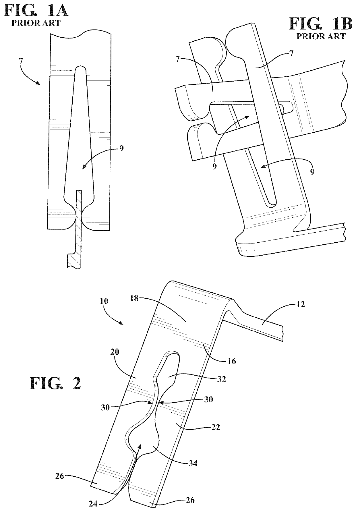
[0015]Referring now to the Figures, where like numerals are used to designate like structure unless otherwise indicated, a portion of a prior art control valve for controlling a flow of a fluid medium is generally shown in FIG. 1A. The prior art control valve includes a prior art electrical connector 7. As illustrated in FIG. 1A, the prior art electrical connector 7 includes an elongated slot 9 along a portion of a length of the prior art electrical connector 7. During shipping, two or more prior art electrical connectors 7 become tangled as one prior art electrical connector 7 may become unintentionally inserted sideways into or get “caught” in the slot 9 of another prior art electrical connector 7, as shown in FIG. 1B. As a result of this entanglement, one or more of the prior art electrical connectors 7 may become deformed and rendered unusable when pulled apart for use.

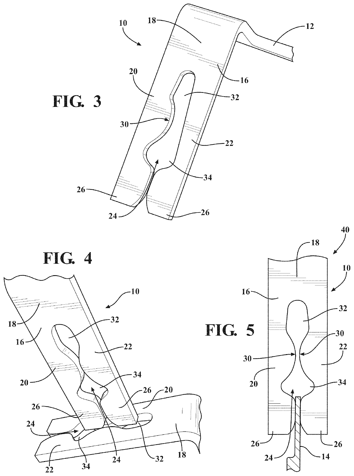
[0016]An electrical connector 10 designed to prevent entanglement is illustrated in FIGS. 2-5. The electrical c...


PUM


Abstract

An electrical connector includes a blade terminal configured to establish an electrical circuit. The electrical connector also includes a receiving terminal coupled to the blade terminal. The receiving terminal includes a bridge portion, a first leg extending from the bridge portion, and a second leg extending from the bridge portion and separated from the first leg by a slot defined by the bridge portion, the first leg, and the second leg. Moreover, at least one of the first leg and the second leg include a geometric feature extending into the slot such that the slot is configured to prevent insertion of a second electrical connector into the slot.

Description

CROSS-REFERENCE TO RELATED APPLICATIONS[0001]This application claims priority to and all the advantages of U.S. Provisional Patent Application No. 62 / 845,616, filed May 9, 2019, the entire contents of which are hereby incorporated by reference.BACKGROUND OF THE INVENTION1. Field of the Invention[0002]The subject invention relates generally to a control valve and, more specifically, an electrical connector for use in the control valve.2. Description of the Related Art[0003]Conventional vehicle powertrain systems known in the art typically include an engine in rotational communication with a transmission. The engine generates rotational torque which is selectively translated to the transmission which, in turn, translates rotational torque to one or more wheels. Typical transmissions are shifted in discrete steps between a high-torque, low-speed mode for starting a vehicle and a high-speed, low-torque mode for vehicle operation at highway speeds. In a manual transmission, shifting is a...

Claims


Application Information

Patent Timeline
IPC IPC(8): H01R11/05
CPCH01R11/05H01R2201/26H01R13/02H01R13/112F01N2390/02F01N13/18F01N9/00F02M26/53Y02T10/40F02M26/65
Inventor BOGEN, MARTIN P.PREISS, JOHANNES A.
Owner BORG WARNER INC
Why Eureka
Eureka Blog
Learn More