Connector and connector assembly

a technology of connectors and assemblies, applied in the direction of coupling contact members, coupling device connections, coupling/disassembly of coupling parts, etc., can solve the problems of large pressing force on damage or breakage and the operator's difficulty in viewing the mating surface of the housing b>811/b> and

Active Publication Date: 2020-11-12
MOLEX INC
View PDF0 Cites 10 Cited by
  • Summary
  • Abstract
  • Description
  • Claims
  • Application Information

AI Technical Summary

Benefits of technology

[0020]According to the present disclosure, the mating guide part or the like of the connector b...

Problems solved by technology

However, in the known connector, during the mating operation, the housing 811 may be damaged or broken.
Especially, miniaturization and reduction in the size of the board to board connector has recently advanced, making it difficult for the operator to view the mating surface of the housing 811 and the mating surface of the counterpart housing.
In such cases, a part of the mating surface of the housing 811 may receive a large pressing force and become damaged or broken.
Especially, since miniaturization and reduction in the size of the board to board connector has recently advanced, when the thickness of each part of the housing 811 is thin and subj...

Method used


Image

  • Connector and connector assembly
  • Connector and connector assembly
  • Connector and connector assembly

Examples


Embodiment Construction

[0031]An embodiment will be described in detail below with reference to the drawings.

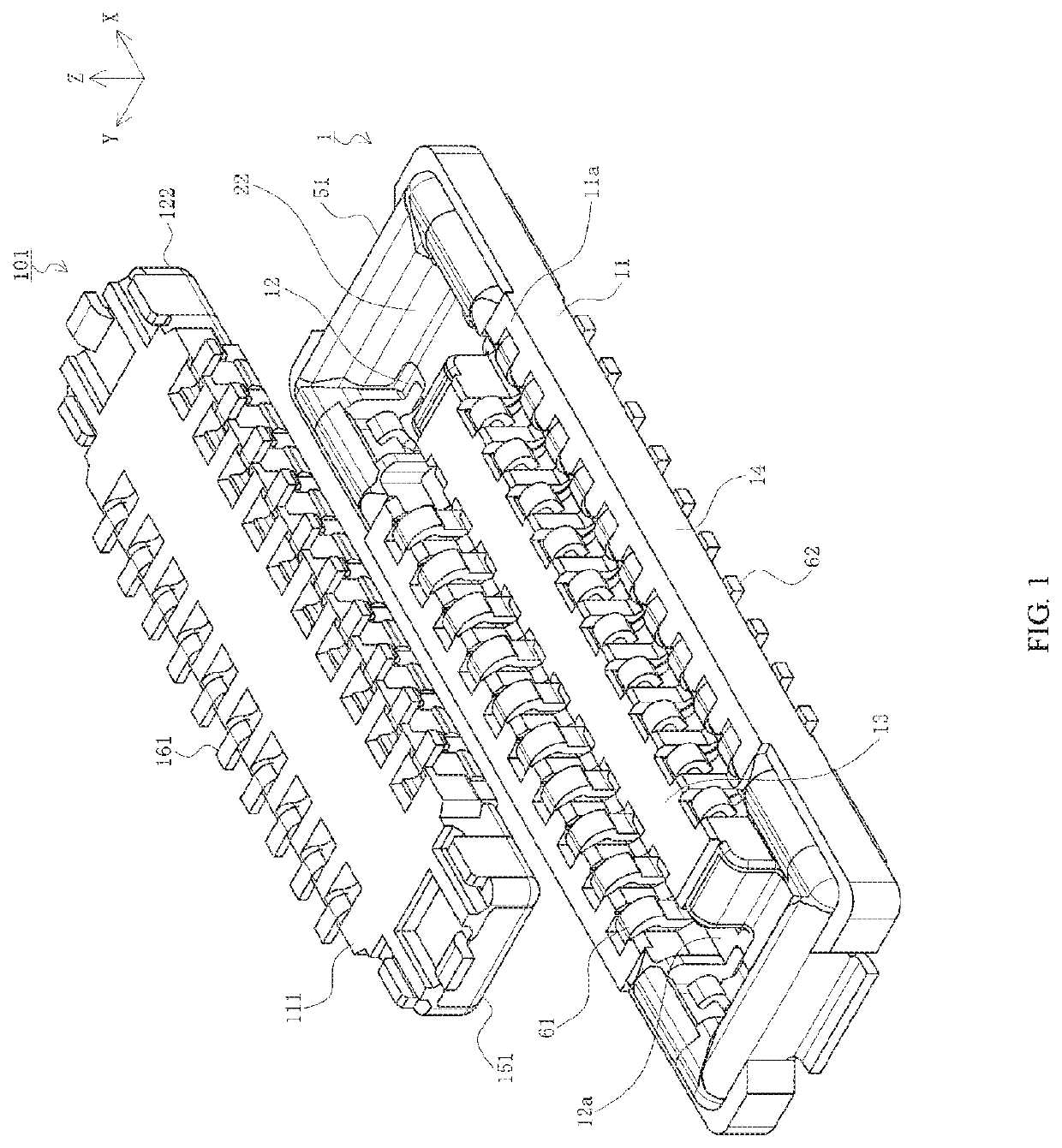
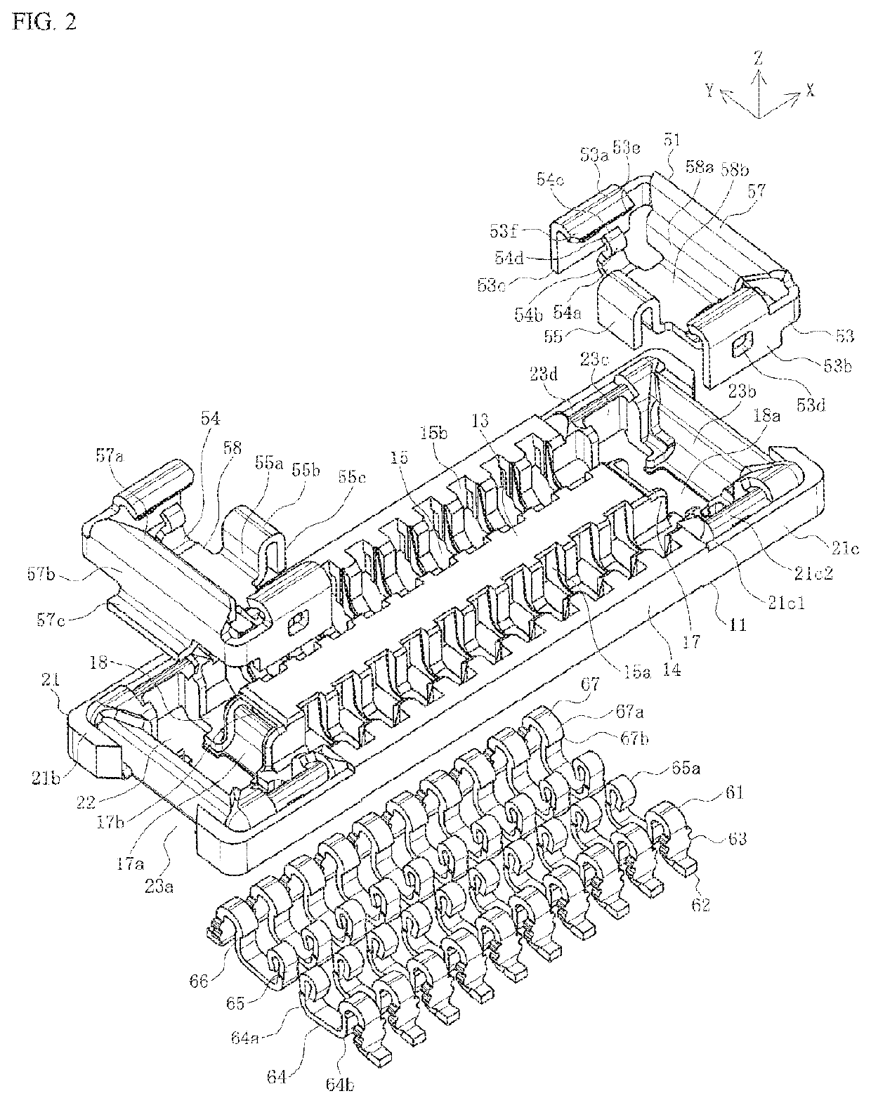
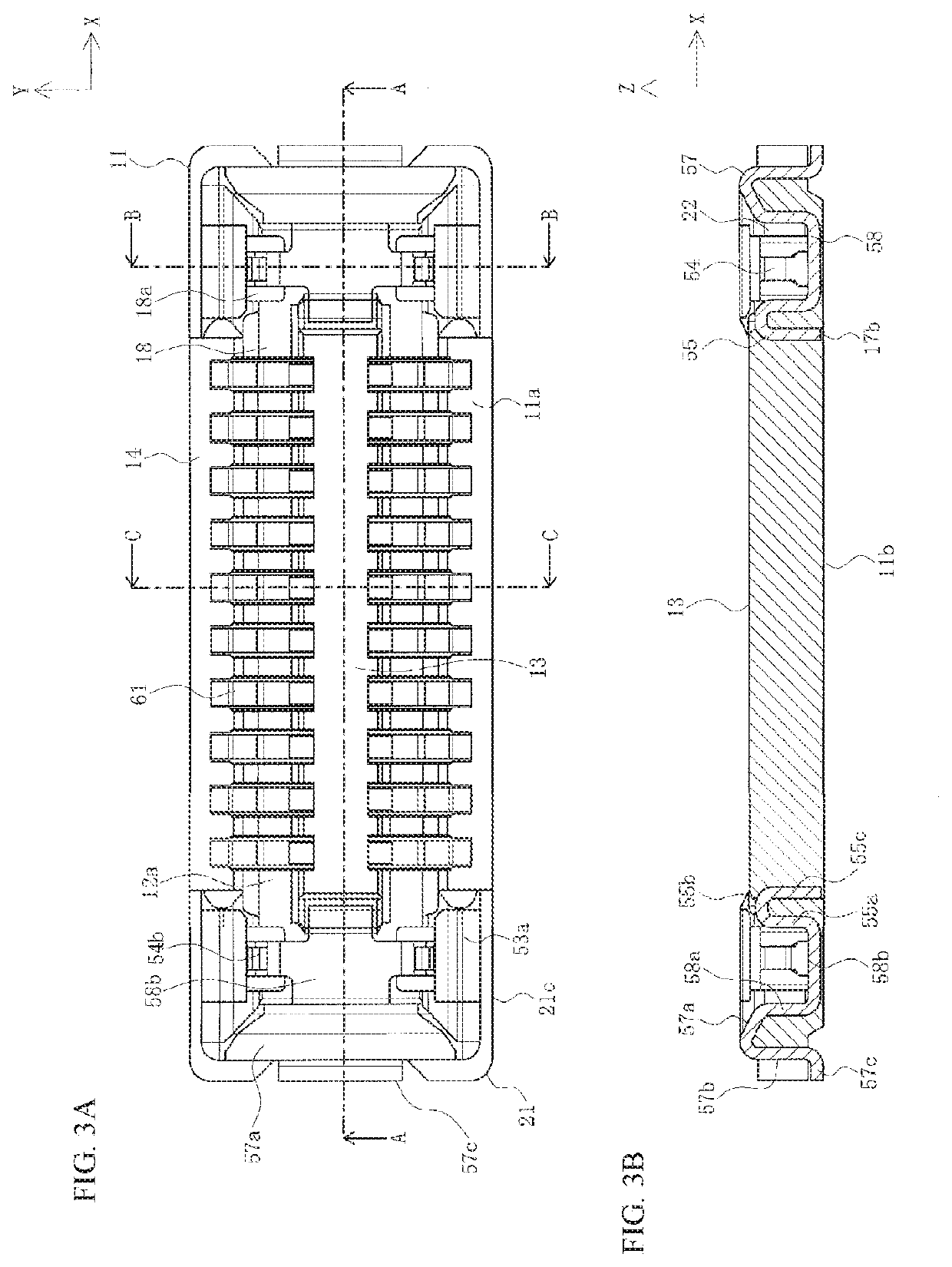
[0032]FIG. 1 is a perspective view illustrating the positional relationship between a first connector and a second connector prior to mating according to the present embodiment when viewed from the second connector side. FIG. 2 is an exploded view illustrating the first connector according to the present embodiment, FIGS. 3A and 3B show views illustrating the first connector according to the present embodiment, and FIGS. 4A and 4B show cross-sectional views illustrating the first connector according to the present embodiment. In FIGS. 3A and 3B, FIG. 3A is a plan view, FIG. 3B is a rear view taken along a line A-A in FIG. 3A. In FIGS. 4A and 4B, FIG. 4A is a cross-sectional view taken along a line B-B in FIG. 3A, and FIG. 4B is a cross-sectional view taken along a line C-C in FIG. 3A.

[0033]In the figures, 1 is a connector of the present embodiment and is the first connector serving as one of a pair ...


PUM


Abstract

A connector body includes mating guide parts having mating recesses into which counterpart mating guide parts are inserted, the reinforcing bracket includes a body part attached to end wall parts of the mating guide parts, and a pair of left and right connection arms connected to both ends of the body part, the connection arms extending to the longitudinal center of the connector body and being attached to side wall parts of the mating guide parts, the connection arm includes a side plate part and a side wall upper cover part connected to an upper end of the side plate part, at least a part of the outside of the side plate part is covered with an outside part of the side wall part, and the side wall upper cover part is curved such that a tip faces the mating recess and covers at least a part of the upper surface of the inside part of the side wall part.

Description

RELATED APPLICATION[0001]This application claims priority to Japanese Application Serial No. 2019-088277, filed on May 8, 2019, which is incorporated by reference in its entirety.TECHNICAL FIELD[0002]The present disclosure relates to a connector and a connector assembly.BACKGROUND ART[0003]Conventionally, connectors such as board to board connectors, etc., have been used to electrically connect pairs of parallel circuit boards together. Such connectors are attached to each mutually facing surface on pairs of circuit boards and mated together so as to be connected. In addition, technology has been proposed in which reinforcing brackets attached to both ends function as locking members to maintain a mated state with the counterpart connector (for example, see Patent Document 1).[0004]FIG. 10 is a perspective view illustrating a known connector.[0005]In the figure, reference numeral 811 denotes a housing of a connector mounted to a circuit board not illustrated, and the connector is ma...

Claims


Application Information

Patent Timeline
IPC IPC(8): H01R12/71H01R13/631H01R13/516
CPCH01R13/516H01R12/716H01R13/631H01R12/7005H01R12/771H01R13/62H01R24/00H01R12/73H01R13/56H01R13/20H01R12/71H01R12/58H01R13/2407
Inventor TANAKA, DAIKISASAYAMA, NAOTO
Owner MOLEX INC
Why Eureka
Try Eureka