
Signal processing device, radar device and signal processing method

Active Publication Date: 2020-11-19
DENSO TEN LTD
View PDF4 Cites 5 Cited by
  • Summary
  • Abstract
  • Description
  • Claims
  • Application Information

AI Technical Summary

Benefits of technology

The patent aims to reduce erroneous detection of a target while suppressing an increase in signal processing load. The method involves using a technology that can achieve this.

Problems solved by technology

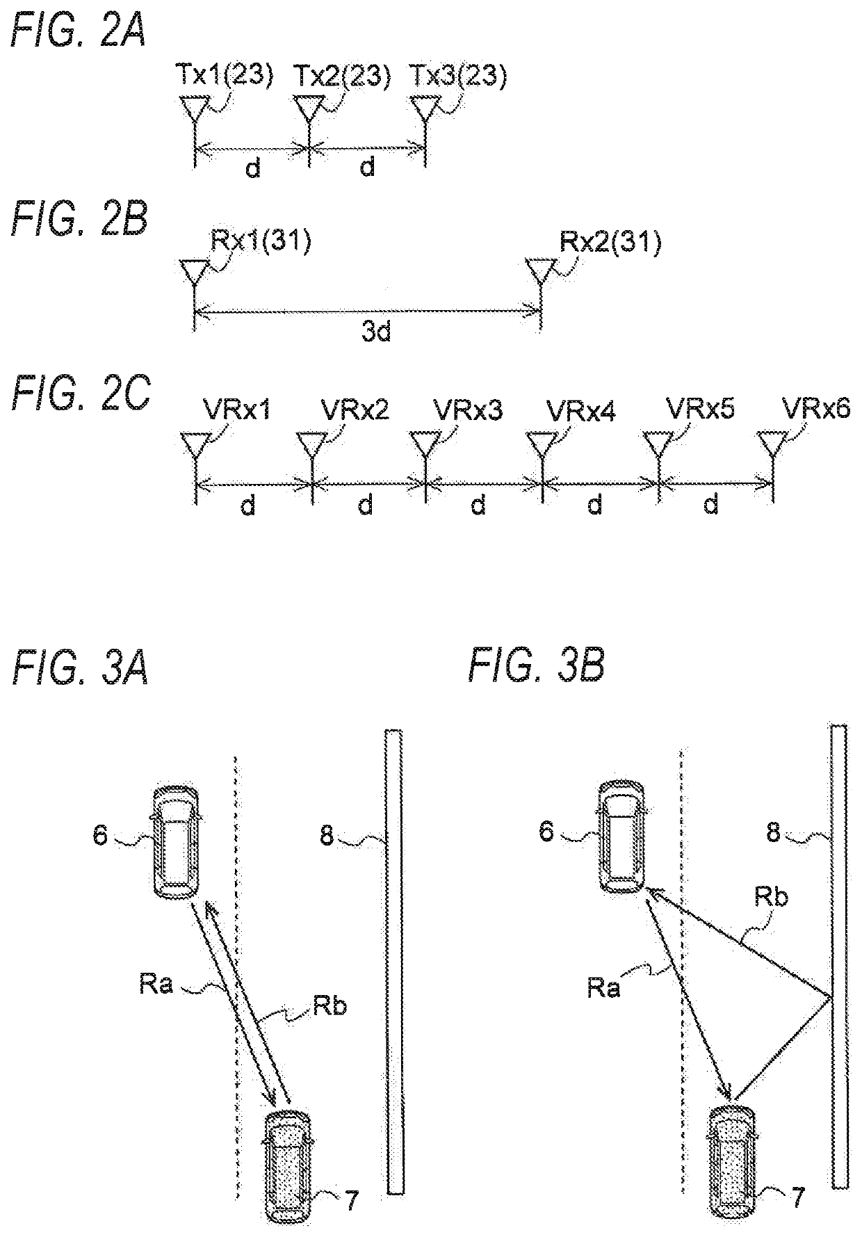
However, radio waves received by the radar device include radio waves whose outward paths and return paths do not match each other, and a target that is not originally present (i.e. a ghost) may be erroneously detected.

Method used


Image

  • Signal processing device, radar device and signal processing method
  • Signal processing device, radar device and signal processing method
  • Signal processing device, radar device and signal processing method

Examples


Embodiment Construction

[0023]Hereinafter, an exemplary embodiment of the present invention will be described in detail with reference to the drawings.

[0024]

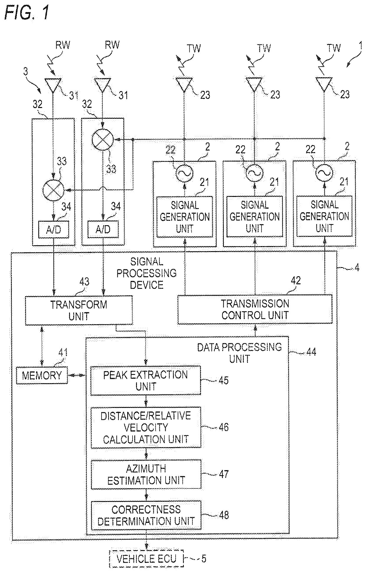
[0025]FIG. 1 shows a configuration of a radar device 1 according to an embodiment of the present invention. The radar device 1 may be mounted on a moving body, such as a vehicle, a robot, an aircraft, or a watercraft. In the present embodiment, the radar device 1 is placed on a vehicle, such as an automobile. Hereinafter, the vehicle on which the radar device 1 is placed is referred to as the given vehicle.

[0026]The radar device 1 is used to detect targets around a given vehicle on which the radar device 1 is mounted, such as other vehicles, road signs, guardrails, and people. A detection result of a target is output to a storage device of the given vehicle or a vehicle electronic control unit (ECU) 5 that controls behaviors of the given vehicle. The detection result of the target is used in vehicle control, such as, for example, a pre-crash safety sys...


PUM


Abstract

A signal processing device, includes: an azimuth estimation unit configured to estimate an arrival azimuth of a radio wave based on a reception signal of plural antennas; an estimated reception signal calculation unit configured to calculate an estimated reception signal based on an estimation result of the arrival azimuth, for comparison with the reception signal; a residual signal calculation unit configured to calculate a residual signal which is a difference between the reception signal and the estimated reception signal; and a determination unit configured to determine whether the estimation result of the arrival azimuth is correct based on the residual signal.

Description

CROSS-REFERENCE TO RELATED APPLICATIONS[0001]This application is based upon and claims the benefit of priority from prior Japanese patent application No. 2019-090809, filed on May 13, 2019, the entire contents of which are incorporated herein by reference.BACKGROUNDTechnical Field[0002]The present invention relates to a signal processing device, a radar device, and a signal processing method.Related Art[0003]A radar device transmits a radio wave, and measures a distance, a relative velocity, and an azimuth of a target upon receiving the radio wave reflected from the target. When the distance and the like relating to the target is measured, it is assumed that a path along which the radio wave transmitted from the radar device reaches the target (outward path) matches a path along which the radio wave reflected by the target returns to the radar device (return path). However, radio waves received by the radar device include radio waves whose outward paths and return paths do not match...

Claims


Application Information

Patent Timeline
IPC IPC(8): G01S13/72H04B7/0413G01S7/288
CPCG01S7/288G01S2007/2883H04B7/0413G01S13/726G01S13/931G01S13/584G01S13/4454G01S13/4418G01S13/343G01S7/4056G01S7/403G01S7/356G01S7/4026G01S7/2883
Inventor ISHIKAWA, HIROKI
Owner DENSO TEN LTD
Learn More