Supercharge Your Innovation With Domain-Expert AI Agents!

Wearable injection device

a technology of injection device and wearable body, which is applied in the direction of intravenous device, infusion needle, infusion syringe, etc., can solve the problems of not being suitable for disposable devices, involving delicate parts, and based on rather expensive mechanical and electronic parts, and achieves the effect of cheap manufacturing

Pending Publication Date: 2020-12-10
SUBCUJECT APS
View PDF2 Cites 2 Cited by
  • Summary
  • Abstract
  • Description
  • Claims
  • Application Information

AI Technical Summary

Benefits of technology

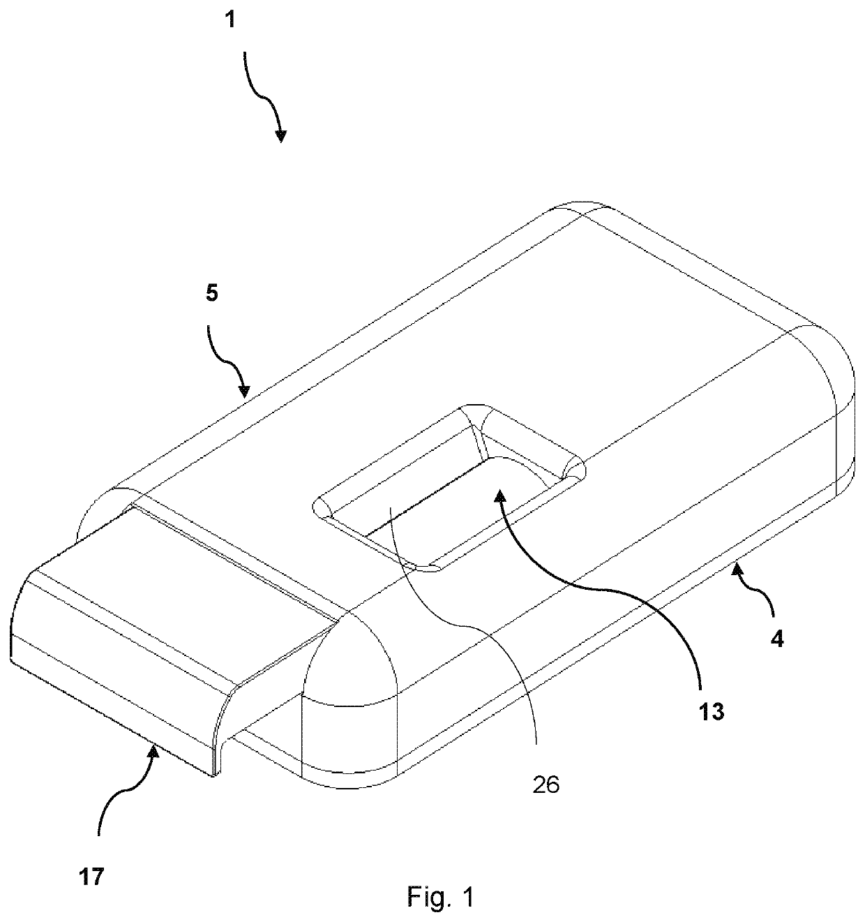
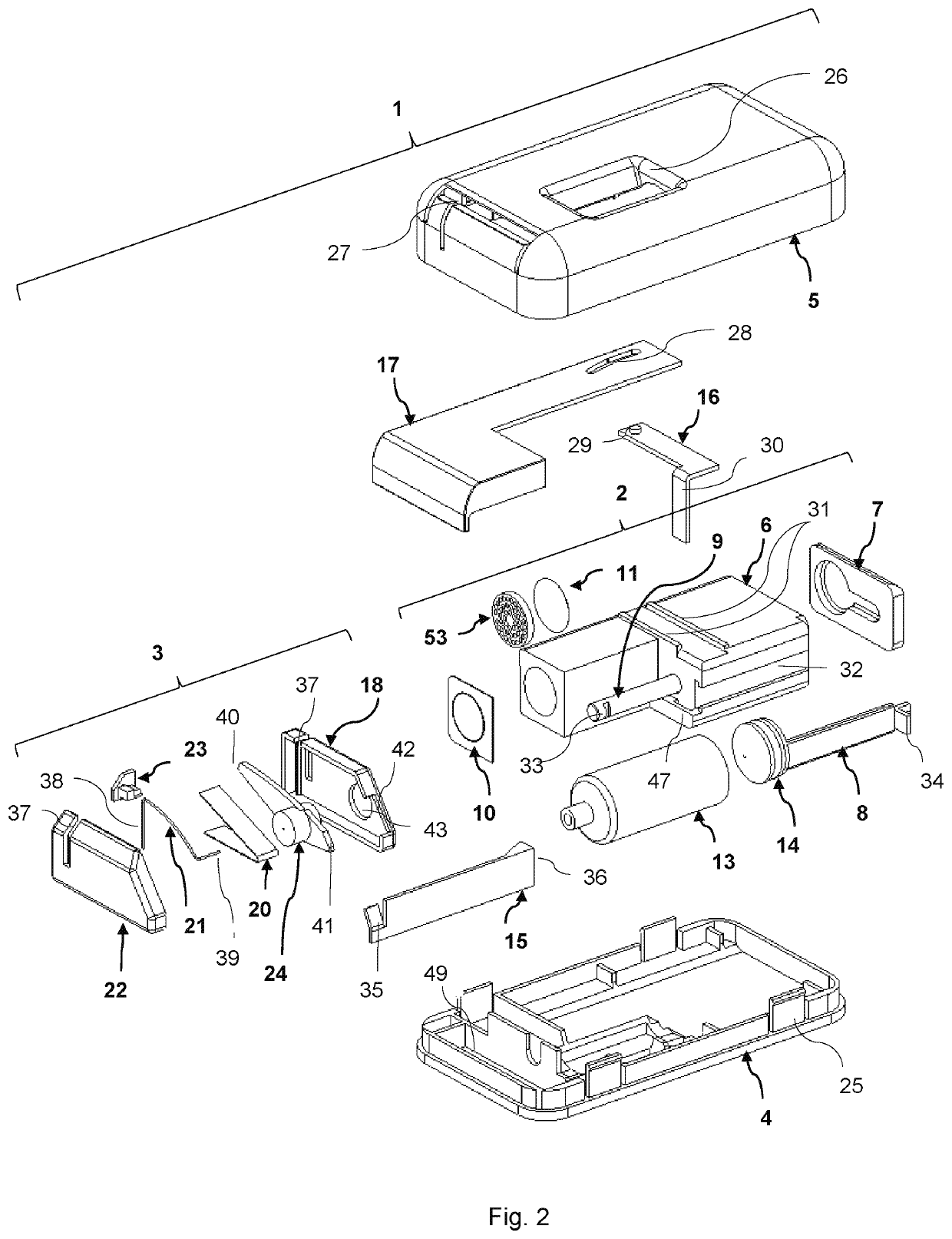
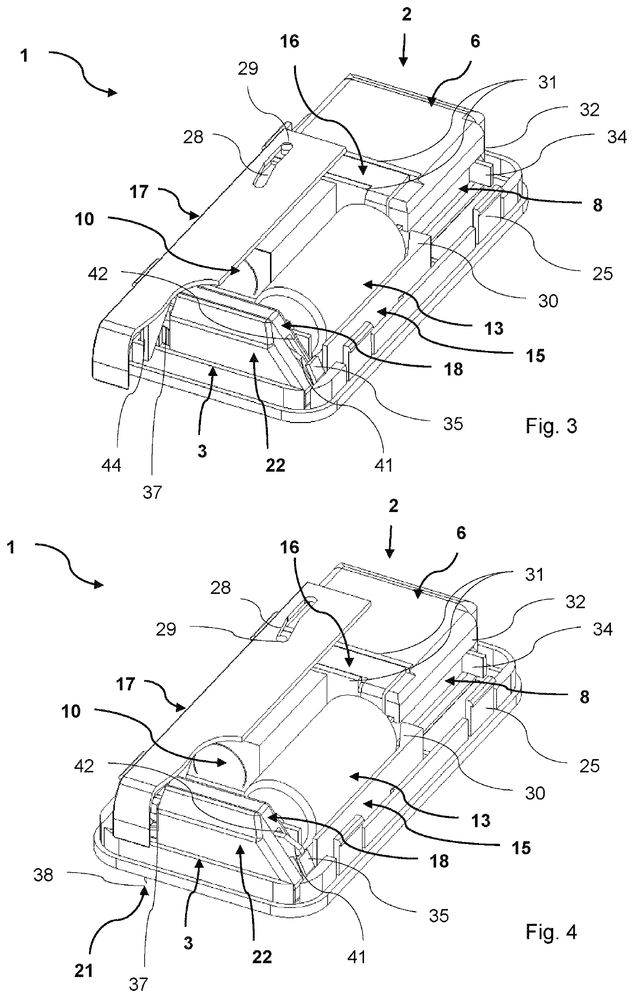
[0008]It is a first objective of the invention to provide a wearable injection device based on an osmotic engine, which is small, cheap to manufacture and which is capable of accommodating large injections over a controlled period of time.
[0009]It is a second objective of the invention to provide a needle system for a wearable injection device, which is simple, which can be sterilized separately, and which accommodates both insertion and retraction of the needle.

Problems solved by technology

This device is based on rather expensive mechanical and electronically parts and seems to be rather complicated and indeed not suitable for a disposable device.
Furthermore, the device includes some delicate parts such as a very thin wire, which is winded and un-winded a large number of times.
Also, this mechanism seems to be very expensive and is not suited for use in a disposable device.
Though the insertion method is very well described it is unclear how the needle should be removed from the skin again if not just by removing the entire device.
Another disadvantage is that the needle is not encapsulated so that it can be sterilized separately, but the entire device must be sterilized.

Method used


Image

  • Wearable injection device
  • Wearable injection device
  • Wearable injection device

Examples


embodiment 301

[0128]An embodiment 301 having a larger membrane area is shown in FIGS. 19-22. As can be seen in FIG. 20, a membrane unit 380 is composed by a number of hollow fibre membranes 381 and two end caps 387, and the hollow fibres 381 are open in one end and closed in the other end. Thereby, a considerable larger membrane surface area can be provided compared with a device using a flat sheet, and it is easy to vary the number of hollow fibres 381 according to the desired injection time. Another advantage is that the hollow fibres are self-supporting, whereby a separate support for the membranes so that they can withstand the pressure in the actuator is avoided. The membrane unit 380 is arranged tightly in an end-housing 306, which is welded to a main-housing 307 such that the open end 385 of the hollow fibres 381 is pointing towards the low-pressure chamber 345 and such that the membrane unit 380 is separating the low-pressure 345 and high-pressure 346 chambers. In some embodiments, the me...

first embodiment

[0138]In another embodiment of the needle assembly 403, the cartridge 413 and the needle assembly 401 do not rotate when the wearable injection device 401 is activated. In this embodiment, the second needle end 473 simply moves up and down relative to the first needle end 472 and guided by the pin 475 when the device is triggered, which in turn will allow the needle assembly 403 to be smaller and take up less space. At the same time, this will bend the intermediate part 471 of the needle connector 424 more than what is the case in the FIGS. 25-27 show an embodiment of the needle assembly 503 with an inlet needle 588 for connecting to the cartridge 513 and an outlet needle 521 with a sharpened end 538 (see FIG. 26) to be inserted in the subject to be injected, in which the two needles 588, 521 are disconnected until the device is activated. The inlet needle 588 is inserted in a horizontally moving part 512 with a hole in the side (not visible) or they are moulded as one part, and th...


PUM


Abstract

A wearable injection device for subcutaneous injection of a therapeutic agent, wherein the dose is injected over a specified period of time after the device is activated.

Description

RELATED APPLICATION DATA[0001]This application is a divisional application of U.S. application Ser. No. 16 / 070,773. filed Jul. 17, 2018, which is a national phase of International Application No. PCT / DK2017 / 050011, filed Jan. 20, 2017, which claims the benefit of Denmark Application Nos. PA 2016 00060, filed Jan. 28, 2016, PA 2016 00134, filed Mar. 2, 2016, PA 2016 00372, filed Jun. 23, 2016, and PA 2016 00585, filed Oct. 3, 2016, all of which are incorporated herein by reference in their entireties.FIELD OF INVENTION[0002]The invention relates to a wearable injection device for subcutaneous injection of a therapeutic agent, wherein the dose is injected over a specified period of time.BACKGROUND[0003]During the recent years, self-injection of various therapeutic agents by means of auto injectors on a daily, weekly, monthly or just on a one-time basis has become more common. As the effect of a therapeutically effect of a therapeutic agent can be slowed down to last longer, it is ofte...

Claims


Application Information

Patent Timeline
Patent Type & Authority Applications(United States)
IPC IPC(8): A61M5/142A61M5/24
CPCA61M2005/14252A61M2005/1585A61M5/2455A61M2005/2474A61M2005/14513A61M5/2466A61M5/14248A61M5/1452A61M2005/1581A61M5/14526A61M5/2429A61M5/14244
Inventor MØLLER, CLAUS SCHMIDT
Owner SUBCUJECT APS
Features
  • R&D
  • Intellectual Property
  • Life Sciences
  • Materials
  • Tech Scout
  • Unparalleled Data Quality
  • Higher Quality Content
  • 60% Fewer Hallucinations
Learn More