Lifting-magnet attachment magnetic pole unit, steel-lifting magnetic-pole-equipped lifting magnet, steel material conveying method, and steel plate manufacturing method

Pending Publication Date: 2020-12-10
JFE STEEL CORP
View PDF0 Cites 0 Cited by
  • Summary
  • Abstract
  • Description
  • Claims
  • Application Information

AI Technical Summary

Benefits of technology

[0044]When only one steel material is to be lifted, aspects of the present invention can prevent the occurrence of magnetic flux saturation in the uppermost piece of steel materials stacked in layers. Therefore, even when the steel materials are of a plate thickness of 20 mm or less, only the uppermost piece of those stacked in layers can be easily lifted with the magnetic-pole-equipped lifting magnet. Additionally, since the entire magnetic flux produced in the coil can be used to lift the steel material at the top,

Problems solved by technology

Then, a plurality of plates are simultaneously attracted to the lifting magnet and this leads to a loss of efficiency in conveying steel materials and pos

Method used


Image

  • Lifting-magnet attachment magnetic pole unit, steel-lifting magnetic-pole-equipped lifting magnet, steel material conveying method, and steel plate manufacturing method
  • Lifting-magnet attachment magnetic pole unit, steel-lifting magnetic-pole-equipped lifting magnet, steel material conveying method, and steel plate manufacturing method
  • Lifting-magnet attachment magnetic pole unit, steel-lifting magnetic-pole-equipped lifting magnet, steel material conveying method, and steel plate manufacturing method

Examples


first embodiment

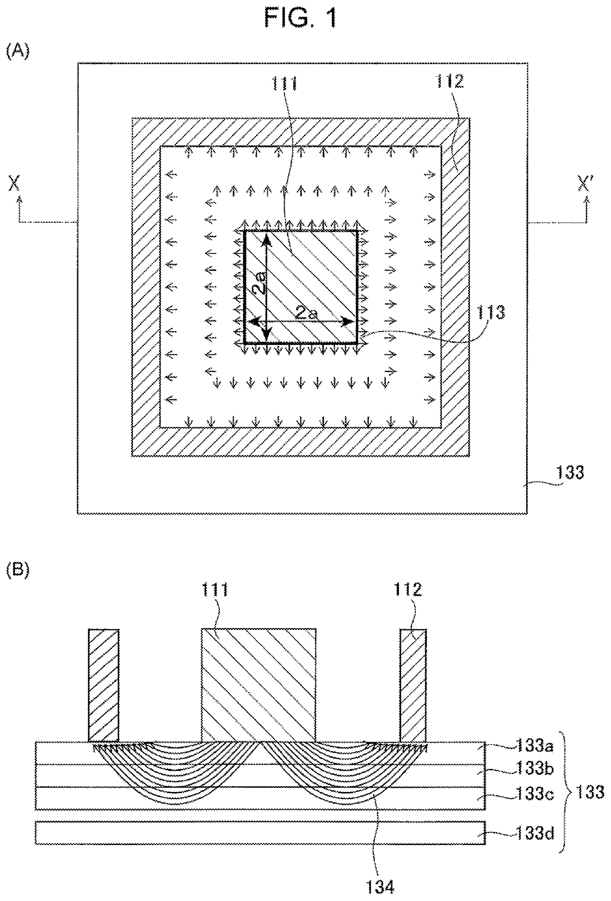
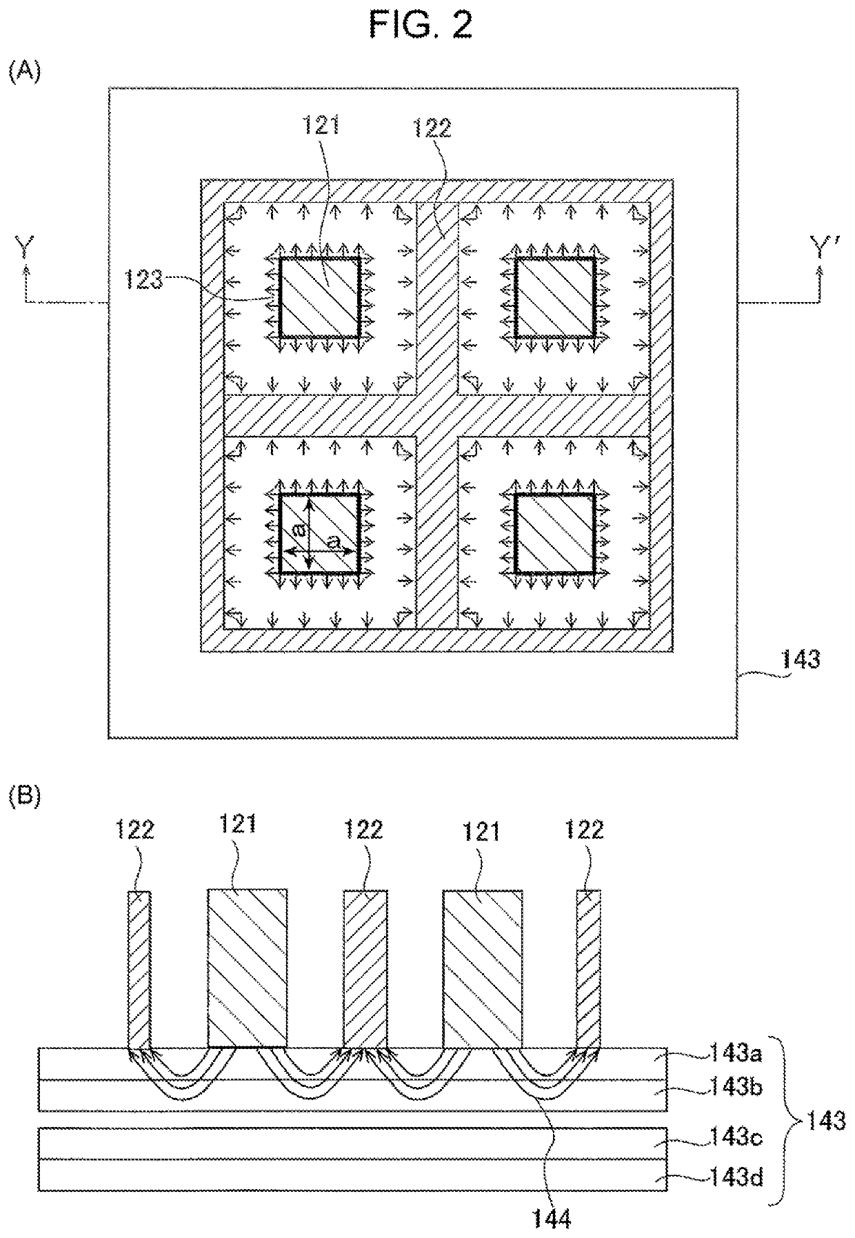
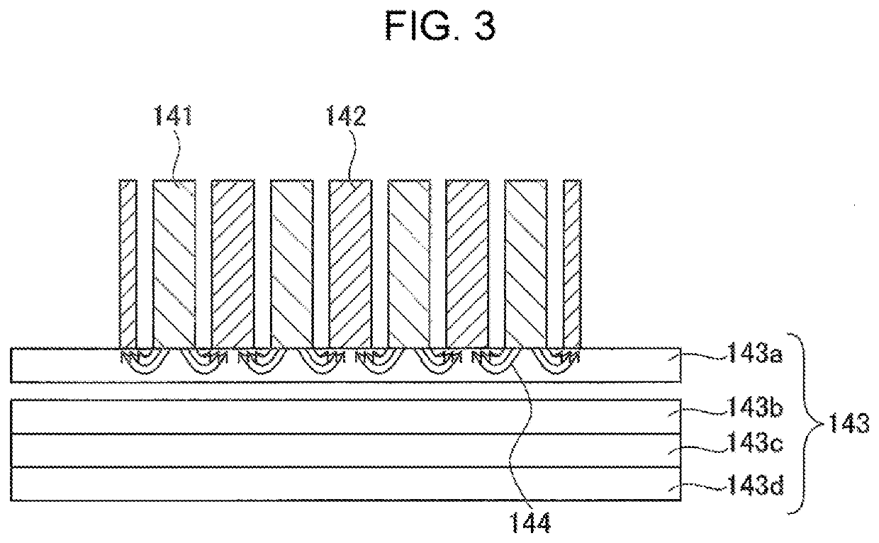
[0059]A lifting-magnet attachment magnetic pole unit according to a first embodiment is a lifting-magnet attachment magnetic pole unit for a lifting magnet used to lift and convey a steel material with magnetic force. The lifting-magnet attachment magnetic pole unit includes a first split magnetic pole that is in contact with an iron core of the lifting magnet and has a branched structure, and a second split magnetic pole that is in contact with a yoke of the lifting magnet and has a branched structure. The first and second split magnetic poles are alternately arranged. The dimensions of the first split magnetic pole may satisfy Inequality (1) described below. The distance between the first and second split magnetic poles alternately arranged may be 30 mm or less. The first and second split magnetic poles may each have a plate thickness of 20 mm or less.

[0060]A steel-lifting magnetic-pole-equipped lifting magnet according to the first embodiment is a magnetic-pole-equipped lifting m...

second embodiment

[0087]A lifting-magnet attachment magnetic pole unit and a steel-lifting magnetic-pole-equipped lifting magnet according to a second embodiment are configured basically the same as those of the first embodiment, but differ therefrom in that the first split magnetic pole includes at least one movable magnetic pole and a fixed magnetic pole in a region adjacent to the movable magnetic pole. The fixed magnetic pole is disposed on a surface in contact with the steel material. The movable magnetic pole is of a movable type. The fixed magnetic pole has dimensions satisfying Inequality (2) described below.

[0088]The second embodiment of the present invention can control the number of steel materials to be lifted by one magnetic-pole-equipped lifting magnet, as described above, such that, for example, only one piece of steel material is lifted or only a desired number of (e.g., two or three) pieces of steel material are lifted. The present inventors completed aspects of the present invention...

example 1

[0141]FIG. 7 schematically illustrates a configuration of a lifting-magnet attachment magnetic pole unit according to the first embodiment of the present invention, used in Example 1. FIG. 7(A) is a plan view of the lifting-magnet attachment magnetic pole unit, as viewed from the underside, FIG. 7(B) is a cross-sectional view taken along line D-D′ in FIG. 7(A), and FIG. 7(C) is a cross-sectional view taken along line E-E′ in FIG. 7(A).

[0142]In Example 1, as an example of the present invention, a steel plate lifting test was performed using a magnetic-pole-equipped lifting magnet, such as that illustrated in FIG. 6, obtained by attaching the lifting-magnet attachment magnetic pole unit (made of SS400) according to aspects of the present invention illustrated in FIG. 7 to a lifting magnet (not shown) including an inner pole 150 mm in diameter and an outer pole 60 mm in thickness and 500 mm×500 mm in size. The magnetic pole unit is 10 mm thick, and the inner pole and the outer pole hav...


PUM


Abstract

An object is to provide a lifting-magnet attachment magnetic pole unit, a lifting magnet, a steel material conveying method, and a steel plate manufacturing method with which only one or a desired pieces of steel materials can be held. The present invention is a lifting-magnet attachment magnetic pole unit for a lifting magnet used to lift and convey a steel material with magnetic force. The lifting-magnet attachment magnetic pole unit includes a first split magnetic pole that is in contact with an iron core of the lifting magnet and has a branched structure, and a second split magnetic pole that is in contact with a yoke of the lifting magnet and has a branched structure. The first and second split magnetic poles are alternately arranged.

Description

CROSS REFERENCE TO RELATED APPLICATIONS[0001]This is the U. S. National Phase application of PCT / JP2018 / 044025, filed Nov. 29, 2018, which claims priority to Japanese Patent Application 2017-228619, filed Nov. 29, 2017, the disclosures of these applications being incorporated herein by reference in their entireties for all purposes.FIELD OF THE INVENTION[0002]The present invention relates to a lifting-magnet attachment magnetic pole unit used to lift and convey steel materials in such places as steel works and steel plate processing plants, a steel-lifting magnetic-pole-equipped lifting magnet, a steel material conveying method, and a steel plate manufacturing method.BACKGROUND OF THE INVENTION[0003]Steel materials are lifted and conveyed in a plate mill of a steel works. The process carried out in the plate mill is roughly divided into two steps: a rolling step which involves rolling out a block of steel into a steel plate of a desired thickness; and a finishing step which involves...

Claims


Application Information

Patent Timeline
IPC IPC(8): B66C1/06H01F7/13
CPCH01F7/18B66C1/06H01F7/13B66C1/04H01F7/206H01F3/10
Inventor TAKAKI, YUKIKOBAYASHI, MASAKIYOTSUJI, JUNICHI
Owner JFE STEEL CORP
Why Eureka
Try Eureka