Forming apparatus and method of manufacturing article

Active Publication Date: 2020-12-10
CANON KK
View PDF0 Cites 2 Cited by
  • Summary
  • Abstract
  • Description
  • Claims
  • Application Information

AI Technical Summary

Benefits of technology

[0007]The present invention provides, for example, a technique advantageous in s

Problems solved by technology

The imprint apparatus suffers from a problem that a mold slips off a mold holder or a formed pattern breaks unless mold separation is performed under proper control.
Decentering can generate large stress in a mold and hence can be a cause of breakage of the mold.
When the

Method used


Image

  • Forming apparatus and method of manufacturing article
  • Forming apparatus and method of manufacturing article
  • Forming apparatus and method of manufacturing article

Examples


Example

First Embodiment

[0030]The present invention relates to a forming apparatus that performs a forming process of forming a curable composition (to be also simply referred to as a “composition” hereinafter) on a substrate. A forming process can include a supply step of discretely supplying liquid droplets of a composition onto a substrate and a contact step of bringing the composition supplied onto the substrate into contact with a member as a mold (original or template). The forming process can also include a curing step of curing the composition in contact with the mold and a mold separation step of separating the cured component from the mold.

[0031]This embodiment will exemplify an imprint apparatus as a specific example of a forming apparatus. The imprint apparatus is an apparatus for bringing an imprint material supplied onto a substrate into contact with a mold, applying curing energy to the imprint material, and forming a pattern of the cured product to which a concave-convex pat...

Example

Second Embodiment

[0068]A specific method of deciding a first chucking condition, a second chucking condition, and the switching timing between them in step S301 in FIG. 11 will be described below. FIG. 12 is a flowchart of a specific method of deciding a first chucking condition, a second chucking condition, and the timing of changing from the first chucking condition to the second chucking condition (to be referred to as the “switching timing” hereinafter) in step S301.

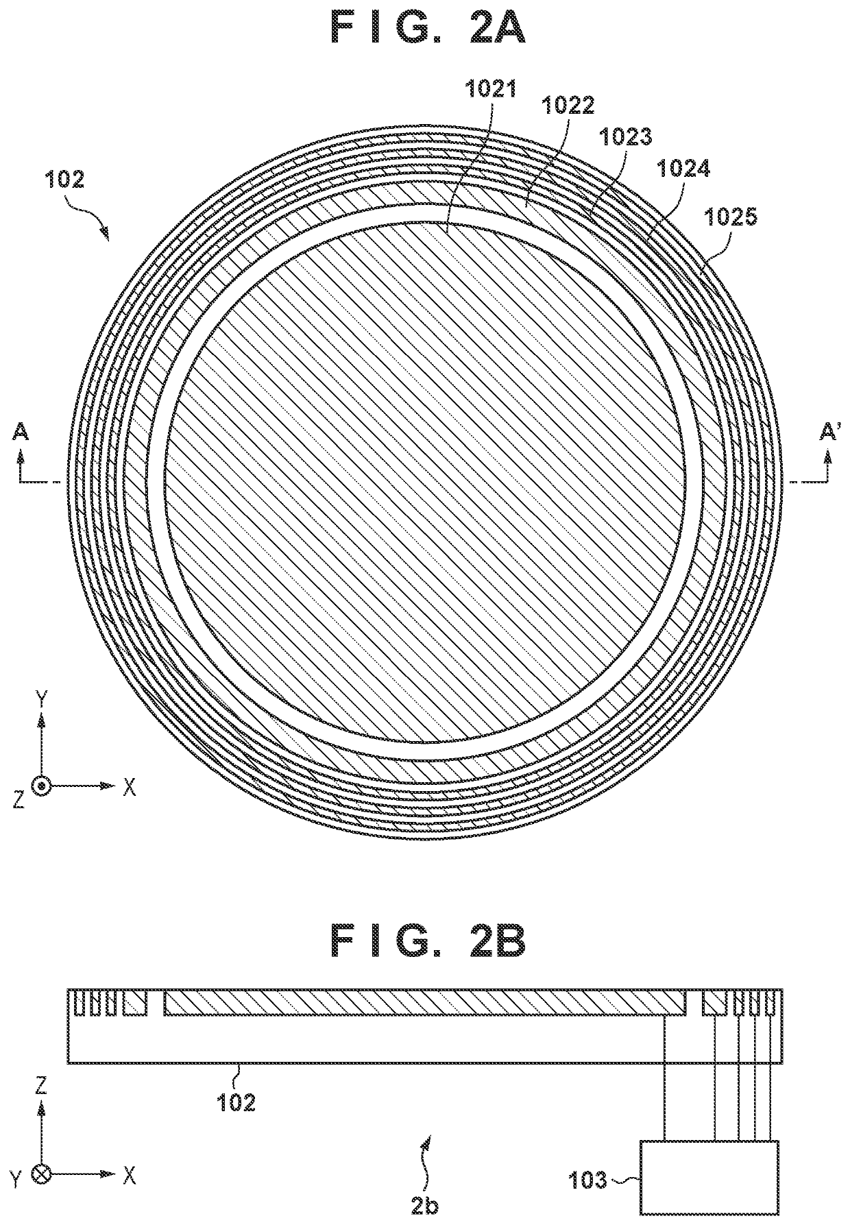
[0069]In step S501, a controller 113 checks, from the shot layout of a substrate 104, which of a first chucking region 1021 to a fifth chucking region 1025 of a substrate holder 102 is present in each shot region. The controller 113 then decides a first chucking condition and a second chucking condition based on the area of a shot region which is occupied by each chucking region or a specific chucking region nearest to the center of a pattern portion 115. If the switching timing is too early, the movement of a substr...

Example

Third Embodiment

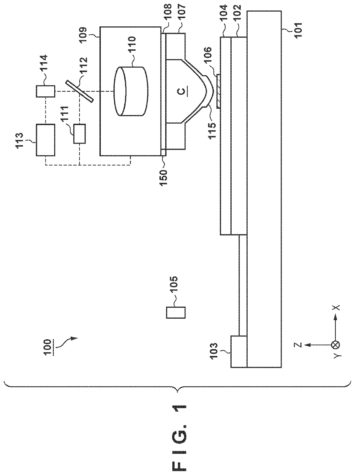
[0076]Another example of a method of deciding a first chucking condition, a second chucking condition, and the switching timing between them in step S301 in FIG. 11 will be described below.

[0077]As shown in FIG. 1, an imprint apparatus 100 according to this embodiment includes a measurement device 150 arranged near a mold holder 108. The measurement device 150 measures a physical amount concerning separation force that is the force required to separate a cured imprint material 106 from a mold 107 in a mold separation step. The measurement device 150 can be, for example, a load cell including a strain body that deforms in proportion to force and a strain gauge that measures the amount of deformation of the strain body.

[0078]FIG. 14 is a flowchart of a specific method of deciding a first chucking condition, a second chucking condition, and the switching timing between them in step S301 according to this embodiment.

[0079]In step S701, a controller 113 checks, from the s...


PUM

PropertyMeasurementUnit
Timeaaaaaaaaaa
Forceaaaaaaaaaa
Separationaaaaaaaaaa

Abstract

A forming apparatus includes a substrate holder having a plurality of chucking regions that chuck a lower surface of the substrate and configured to hold the substrate by chucking the substrate with the plurality of chucking regions, and a controller configured to control execution of a forming process and independently control a chucking force of each of the plurality of chucking regions. The controller controls a chucking force of each of the plurality of chucking regions in a mold separation step so as to make a final mold separation point, at which the mold finally separates from the composition, coincide with a center of a pattern surface of the mold.

Description

BACKGROUND OF THE INVENTIONField of the Invention[0001]The present invention relates to a forming apparatus and a method of manufacturing an article.Description of the Related Art[0002]There is available a forming apparatus that forms a curable composition arranged on a substrate by a forming process. A forming process can include a contact step of bringing a composition on a substrate into contact with a mold, a curing step of curing the composition in contact with the mold, and a separation step of separating the cured composition from the mold.[0003]As a typical example of a forming apparatus, much attention has been paid to an imprint apparatus to be used to manufacture articles such as semiconductor devices. For example, an imprint apparatus using a photo-curing method is configured to supply, first, an imprint material, which is a photo-curable composition, onto a shot region as an imprint region on a substrate. The apparatus then brings a mold into contact with the imprint ma...

Claims


Application Information

Patent Timeline
IPC IPC(8): G03F7/00
CPCG03F7/0002B29C59/02B29C59/002B29C59/026B29C59/022H01L21/30B29L2031/3425H01L21/683G03F7/707B82Y40/00H01L21/687
Inventor SATO, TAKAHIRO
Owner CANON KK
Why Eureka
Try Eureka