
Doping method for semiconductor device

Inactive Publication Date: 2011-02-03
SK HYNIX INC
View PDF3 Cites 2 Cited by
  • Summary
  • Abstract
  • Description
  • Claims
  • Application Information

AI Technical Summary

Benefits of technology

[0007]An exemplary embodiment of the present invention is directed to a doping method for a semiconductor device that may reduce defects by dopi

Problems solved by technology

However, as semiconductor devices become highly integrated, more complicated three-dimensional (3D) structures may be formed.
In this case, if an etch process for forming a 3D structure is performed after a doping process is performed through ion implantation, it may become difficult to form a desired 3D structure because etch characteristics may become different in the area where the doping process is performed.
In this case, however, a portion which is not desired to be doped, that is, an uncontrollable doping region, may be formed.
Also, since the ion implantation method requires high energy and a dopant is implanted through a lattice, defects may be caused due to ion bombardment.
Although the defects may be reduced through a subsequent thermal treatment, the defects are not completely removed.
Therefore, it may be difficult to form a doping region at a desired position without a defect through ion implantation.

Method used


Image

  • Doping method for semiconductor device
  • Doping method for semiconductor device
  • Doping method for semiconductor device

Examples


Embodiment Construction

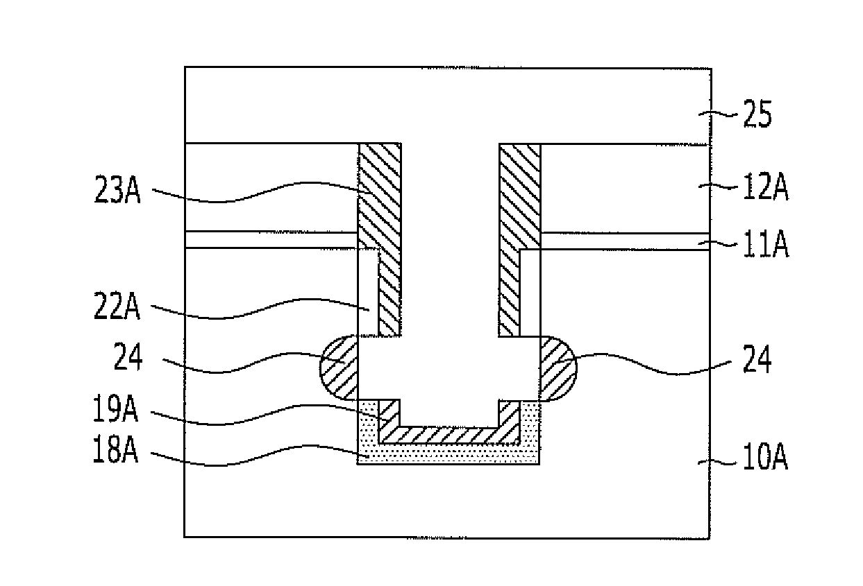
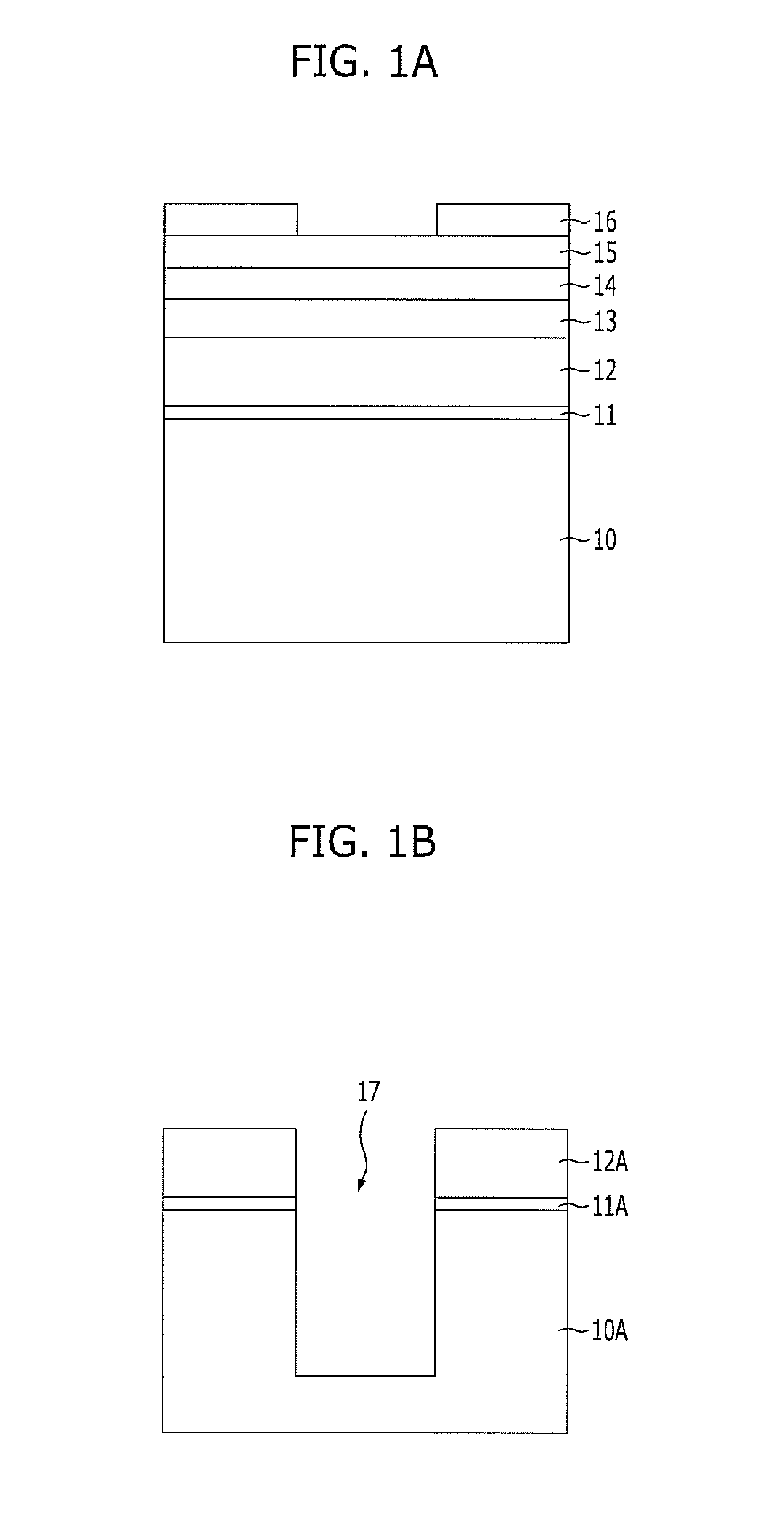
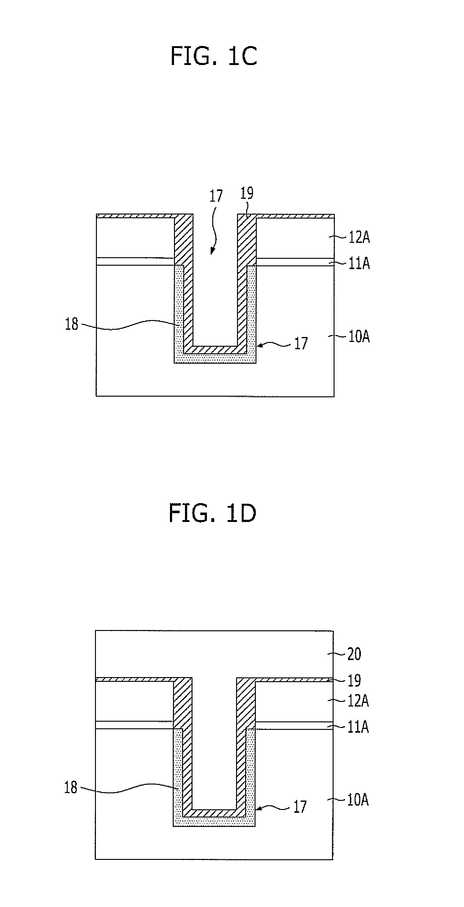
[0012]Exemplary embodiments of the present invention will be described below in more detail with reference to the accompanying drawings. The present invention may, however, be embodied in different forms and may not be construed as limited to the embodiments set forth herein. Rather, these embodiments are provided so that this disclosure will be thorough and complete, and will fully convey the scope of the present invention to those skilled in the art. Throughout the disclosure, like reference numerals refer to like parts throughout the various figures and embodiments of the present invention.

[0013]The drawings are not necessarily to scale and in some instances, proportions may have been exaggerated in order to clearly illustrate features of the embodiments. When a first layer is referred to as being “on” a second layer or “on” a substrate, it not only refers to a case where the first layer is formed directly on the second layer or the substrate, but also a case where a third layer ...


PUM


Abstract

A doping method for a semiconductor device includes forming a trench in a semiconductor substrate, forming a doped layer doped with a dopant over the undoped layer, and forming a doped region into which the dopant is diffused, wherein the doped region is a portion of the semiconductor substrate in contact with the doped layer.

Description

CROSS-REFERENCE TO RELATED APPLICATIONS[0001]The present application claims priority of Korean Patent Application No. 10-2009-0070873, filed on Jul. 31, 2009, which is incorporated herein by reference in its entirety.BACKGROUND OF THE INVENTION[0002]Exemplary embodiments of the present invention relate to a method for fabricating a semiconductor device, and more particularly, to a doping method for a semiconductor device that may dope a particular region without performing an ion implantation process.[0003]Ion implantation is usually used to dope a particular portion, e.g., a junction region, when a semiconductor device is fabricated. The ion implantation may control the doping depth and doping concentration.[0004]However, as semiconductor devices become highly integrated, more complicated three-dimensional (3D) structures may be formed. In this case, if an etch process for forming a 3D structure is performed after a doping process is performed through ion implantation, it may becom...

Claims


Application Information

Patent Timeline
IPC IPC(8): H01L21/22H01L21/762
CPCH01L29/66181H01L21/2257H01L21/225
Inventor KIM, WON-KYU
Owner SK HYNIX INC
Learn More