Method and apparatus for melt flow control in continuous casting mold

Inactive Publication Date: 2006-06-08
THE OHIO STATE UNIV RES FOUND
View PDF5 Cites 1 Cited by
  • Summary
  • Abstract
  • Description
  • Claims
  • Application Information

AI Technical Summary

Benefits of technology

[0007] These needs are met by the present invention, wherein a continuous casting system and a method of operating the system that incorporates the features discussed below are disclosed. By the present invention, the flow of metal is altered in such a way so that it reduces the transfer of the entrained mold flux slag and non-metallic particles to the vicinity of solidifying metal near the mold walls, thereby significant

Problems solved by technology

One especially troublesome flow pattern for the continuous casting of steel under such asymmetric flow conditions involves the tendency of the gas and molten metal that exits the SEN to contact the wider walls of the mold, after which they ascend to

Method used


Image

  • Method and apparatus for melt flow control in continuous casting mold
  • Method and apparatus for melt flow control in continuous casting mold
  • Method and apparatus for melt flow control in continuous casting mold

Examples


Example

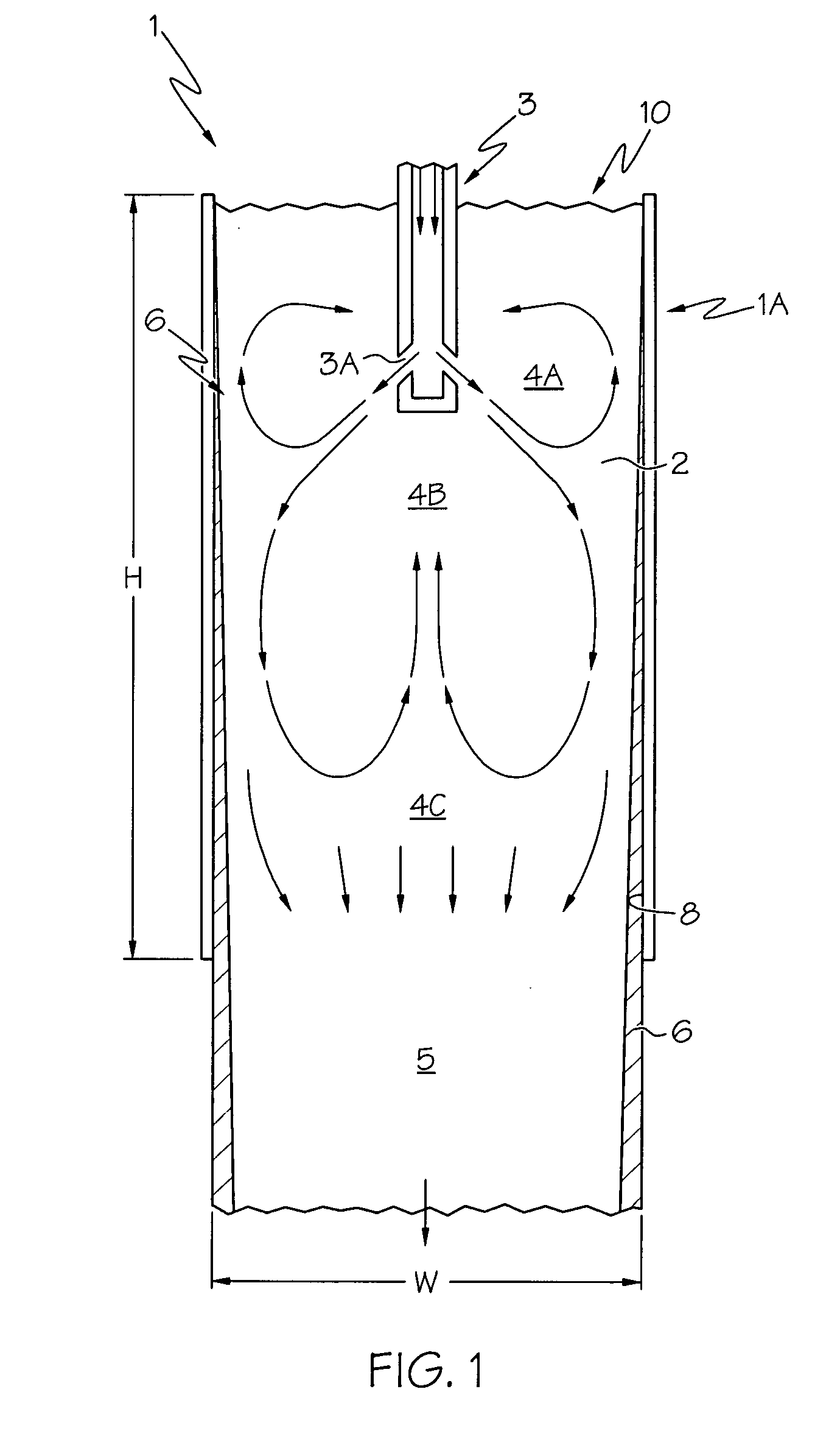
[0032] Referring first to FIG. 1, an elevation view of a conventional continuous casting system showing a general flow pattern in vessel (also referred to as a mold or mold vessel) 1 is shown. Molten metal 2 emerges from discharge ports 3A in SEN 3 and enters the vessel 1, flowing generally along flow lines 4A, 4B and 4C (collectively referred to as flow lines 4). Molten metal 2 then emerges from the vessel 1 as a partially solidified slab 5 in the shape of the vessel 1, which is typically rectangular with a thickness dimension T, height (or length) dimension H and a width dimension W (not presently shown). As the molten metal 2 progresses through the vessel 1, a layer of solidified steel 6 is formed against the interior surfaces 8 of the vessel 1, resulting in the formation of a shell over the freshly cast slab 5. One or more flow modifier members (not presently shown) may be located on either side of the SEN 3, and have traditionally been used to prevent or minimize downward liqui...


PUM

PropertyMeasurementUnit
Timeaaaaaaaaaa
Thicknessaaaaaaaaaa
Flow rateaaaaaaaaaa

Abstract

A method and apparatus for continuous casting of metal. The flow of molten metal is altered to eliminate or reduce the transfer of entrained mold flux slag and non-metallic particles to the vicinity of solidifying metal near the mold walls, thereby resulting in significantly reduced sliver and related defects. Flow modifier members are placed such that their larger surface is more aligned with the larger dimension of the interior volume of the vessel in which the member is placed. In a particular form, the members may be shaped as rectangular plates and placed substantially parallel to the longer interior wall of the vessel.

Description

[0001] This application claims the benefit of U.S. Provisional Application No. 60 / 633,241 filed Dec. 3, 2004.BACKGROUND OF THE INVENTION [0002] The present invention relates generally to the field of continuous casting of steel, and more particularly to a device and method for flowing molten metal in continuous castings that produces fewer defects in the cast product. [0003] In continuous casting of steel (such as plain carbon steel), molten metal is poured from a ladle or tundish into a water-cooled copper mold vessel by using a submerged entry nozzle (SEN). In the continuous casting process, steel begins to solidify as it comes in contact with the walls of the copper mold, the slab descending down the height of the vessel. The thickness of slabs produced in such a mold typically is about 9 to 12 inches (˜230 to 300 mm), whereas in a thin slab caster the thickness is only about 2 to 4 inches (˜50 to 100 mm), while the width is much larger, typically 60 to 72 inches (1500 to 1830 mm...

Claims


Application Information

Patent Timeline
IPC IPC(8): B22D11/10
CPCB22D11/041B22D11/10B22D11/103B22D41/50
Inventor SAHAI, YOGESHWAR
Owner THE OHIO STATE UNIV RES FOUND
Why Eureka
Try Eureka