Methods and system for operating an engine in the presence of engine sensor degradation

a technology of engine sensor and sensor, which is applied in the direction of driver input parameters, control devices, transportation and packaging, etc., can solve the problems of difficulty in accurately estimating the amount of torque generated via the engine, electric machine torque estimation, and driver torque may not be met, so as to increase system cost and complexity, and reduce the possibility of engine stalling

Active Publication Date: 2020-12-17
FORD GLOBAL TECH LLC
View PDF0 Cites 0 Cited by
  • Summary
  • Abstract
  • Description
  • Claims
  • Application Information

AI Technical Summary

Benefits of technology

[0004]By adjusting a load of an electric machine responsive to degradation of an engine sensor, it may be possible to provide the technical result of generating a driveline torque that is close to driver demand torque while reducing the possibility of inducing an engine stall. In particular, a load that the electric machine supplies to the engine may be adjusted to a level that is based on an amount of power that is drawn from an electric energy storage device. At the same time, the requested engine output torque may follow an accelerator pedal position without feedback from and engine airflow sensor. Thus, requested electric machine output torque may be decoupled from the requested engine output torque. The requested electric machine output torque may be limited so that the possibility of an engine stall may be reduced by limiting the requested electric machine torque to a fraction of the requested engine torque.
[0005]The present description may provide several advantages. In particular, the approach may provide a driveline torque that is closer to a requested driver demand torque. Further, the approach may reduce the possibility of an engine stalling when an engine airflow sensor is degraded. In addition, the approach may be implemented without significantly increasing system cost and complexity.

Problems solved by technology

However, if the engine airflow sensor becomes degraded, it may be difficult to accurately estimate the amount of torque that is being generated via the engine.
Further, if the engine torque estimate is in error, then the electric machine torque estimate may be in error such that the driver demand torque may not be met because the electric machine torque may depend on the engine torque estimate to deliver the requested driver demand torque.
Further still, if the electric machine torque cannot be determined with a desired accuracy when an engine torque estimate has lower accuracy, then the vehicle's electric energy storage device may not be charged due to the possibility of inducing an engine stall condition.
Further, the approach may reduce the possibility of an engine stalling when an engine airflow sensor is degraded.

Method used


Image

  • Methods and system for operating an engine in the presence of engine sensor degradation
  • Methods and system for operating an engine in the presence of engine sensor degradation
  • Methods and system for operating an engine in the presence of engine sensor degradation

Examples


Embodiment Construction

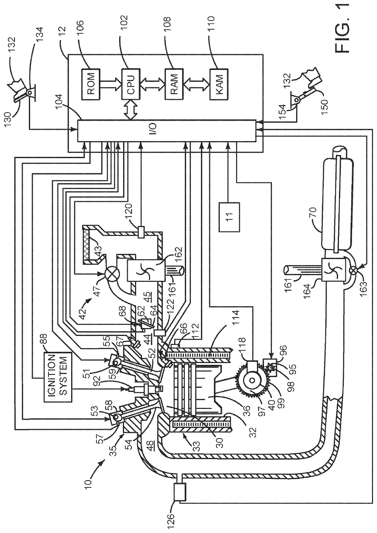
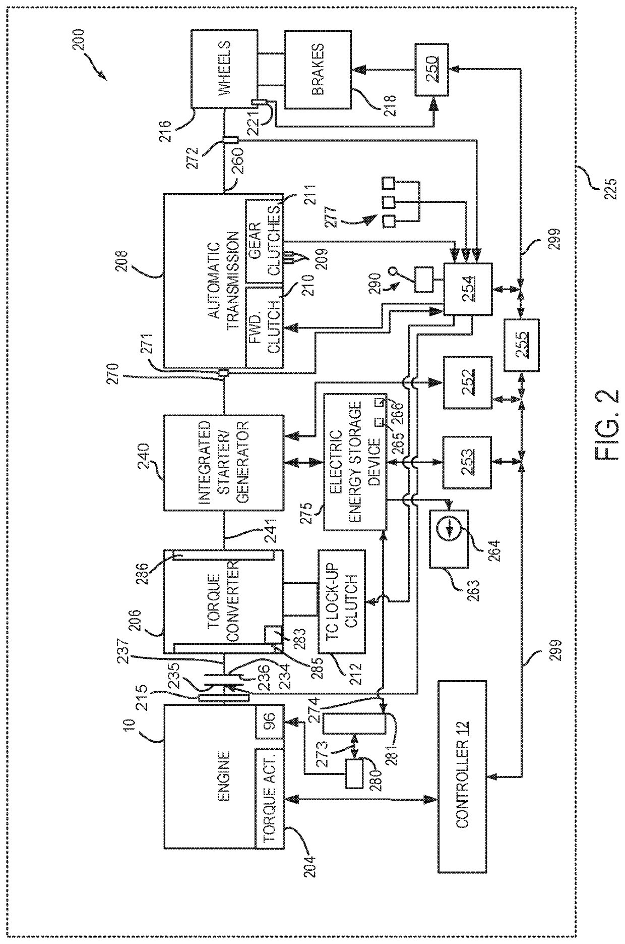
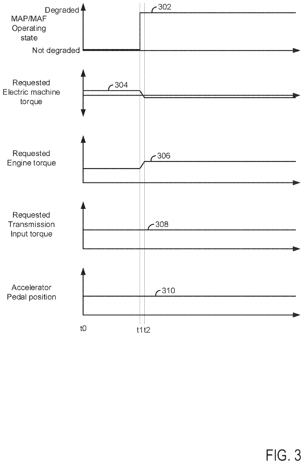
[0014]The present description is related to operating a hybrid vehicle that includes an engine that may be selectively coupled to a driveline that includes an electric machine. The engine and the electric machine may provide propulsive force to move a vehicle. The electric machine may also generate electrical power that may be stored in an electric energy storage device for consumption at a later time. The engine may be of the type shown in FIG. 1 or it may be a diesel engine. The engine and the electric machine may be included in a driveline configuration as shown in FIG. 2. The engine and electric machine may be operated according to the method of FIG. 4 to provide the operating sequence that is shown in FIG. 3. The electric machine torque may be adjusted as a function of accelerator pedal position and torque converter impeller speed as shown in FIG. 5 only when an engine sensor is degraded.

[0015]Referring to FIG. 1, internal combustion engine 10, comprising a plurality of cylinde...


PUM


Abstract

Systems and methods for operating a vehicle that includes an engine and an integrated starter/generator are described. In one example, torque generated via the engine is based on a requested driveline torque and a torque of an electric machine when degradation of an engine sensor is present. The torque generated via the engine may be adjusted responsive to a requested engine torque and a feedback engine torque that is based on output of an engine airflow sensor.

Description

FIELD[0001]The present description relates to methods and a system for a hybrid vehicle that includes an integrated starter / generator for propelling a vehicle and starting an engine.BACKGROUND AND SUMMARY[0002]A hybrid vehicle may include an internal combustion engine and an electric machine to provide propulsion torque. The internal combustion engine may be issued torque commands that may be based on driver demand input torque and vehicle operating conditions. One or more engine sensors may provide feedback information that may be indicative of an amount of torque that is being produced by the engine so that engine torque commands may be adjusted to meet the driver demand torque. For example, the engine sensors may include a manifold absolute pressure (MAP) sensor or a mass airflow (MAF) sensor that indicate the amount of air that is flowing through the engine. The amount of air that is flowing through the engine may be indicative of the amount of torque that is produced by the eng...

Claims


Application Information

Patent Timeline
Patent Type & Authority Applications(United States)
IPC IPC(8): B60W20/50B60W10/02B60W10/06B60W10/08B60W20/10
CPCB60W2520/10B60W2510/305B60W2510/0628B60W2510/0671B60W20/10B60W2540/10B60W10/06B60W10/08B60W10/02B60W2510/242B60W20/50B60W2710/0666B60W2710/083B60W50/029B60W2050/0297Y02T10/62
Inventor JOHRI, RAJITSYED, FAZAL URRAHMAN
Owner FORD GLOBAL TECH LLC
Why Eureka
Try Eureka