
Motor assembly and method for manufacturing the same

a technology of motor assembly and assembly method, which is applied in the direction of machines/engines, mechanical equipment, liquid fuel engines, etc., can solve the problems of reducing the efficiency of the motor assembly, the risk of friction with the inner surface of the inlet body, etc., and achieves accurate and smooth grounding

Active Publication Date: 2020-12-17
LG ELECTRONICS INC
View PDF0 Cites 2 Cited by
  • Summary
  • Abstract
  • Description
  • Claims
  • Application Information

AI Technical Summary

Benefits of technology

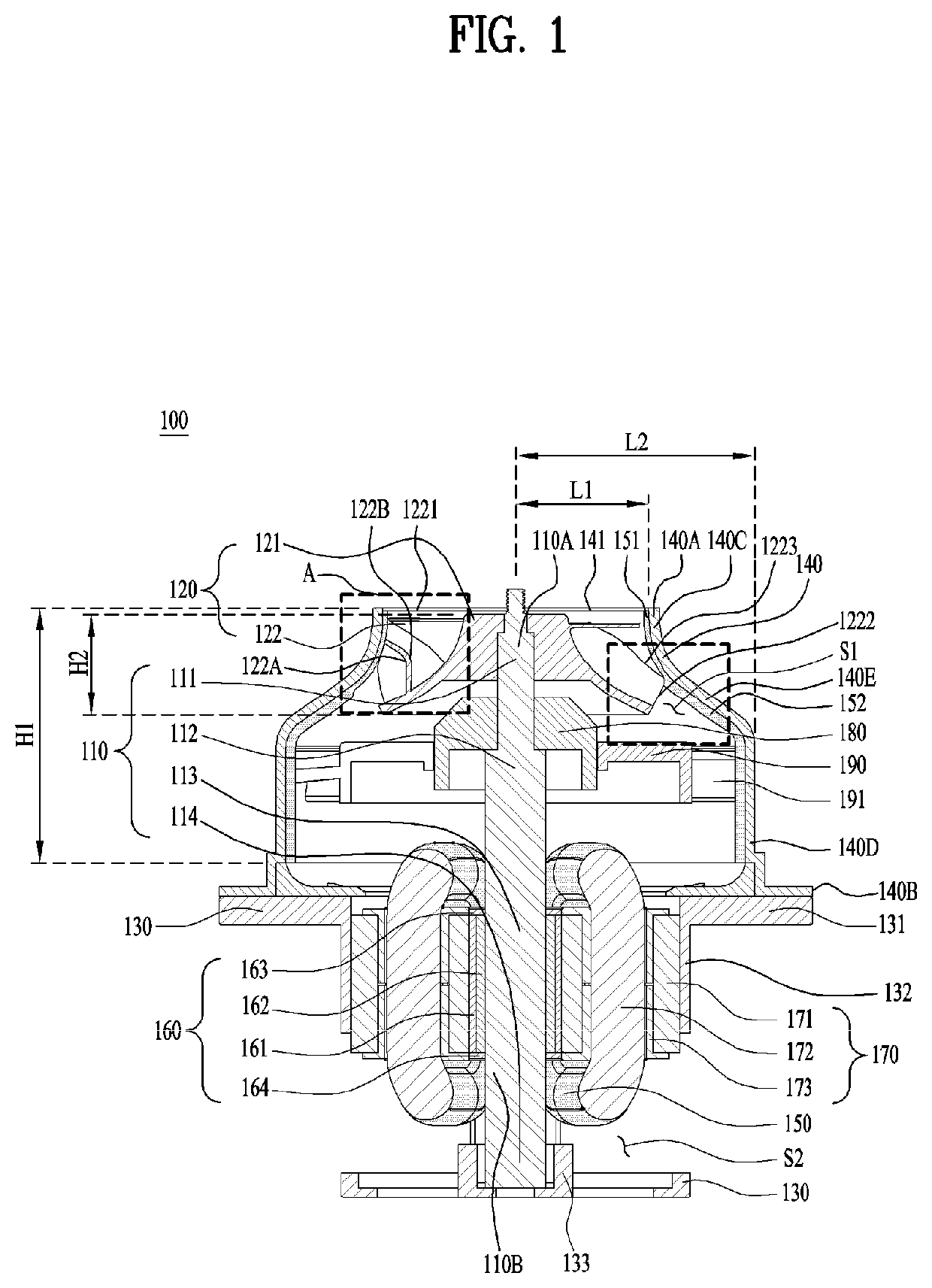
The patent is about a new motor assembly and how to make it more efficient. The goal is to minimize the space between the fan and the inlet body to improve performance.

Problems solved by technology

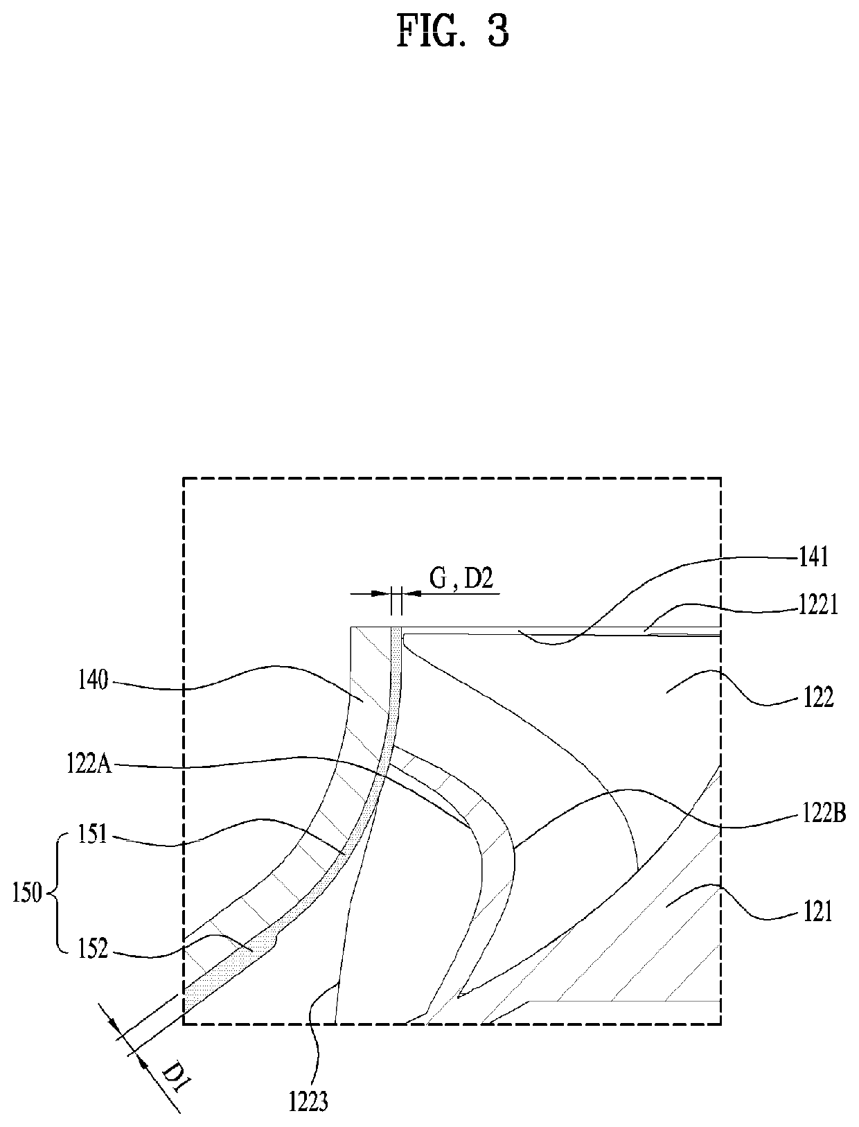
When such tip clearance is too small, there is a risk of friction with the inner surface of the inlet body when the blades rotate.
Further, when the tip clearance is too large, leakage flow or vortex may occur at the tip clearance, which may reduce an efficiency of the motor assembly.

Method used


Image

  • Motor assembly and method for manufacturing the same
  • Motor assembly and method for manufacturing the same
  • Motor assembly and method for manufacturing the same

Examples


Embodiment Construction

[0051]For simplicity and clarity of illustration, elements in the figures are not necessarily drawn to scale. The same reference numbers in different figures denote the same or similar elements, and as such perform similar functionality. Furthermore, in the following detailed description of the present disclosure, numerous specific details are set forth in order to provide a thorough understanding of the present disclosure. However, it will be understood that the present disclosure may be practiced without these specific details. In other instances, well-known methods, procedures, components, and circuits have not been described in detail so as not to unnecessarily obscure aspects of the present disclosure.

[0052]Examples of various embodiments are illustrated and described further below. It will be understood that the description herein is not intended to limit the claims to the specific embodiments described. On the contrary, it is intended to cover alternatives, modifications, and...


PUM

PropertyMeasurementUnit
particle sizeaaaaaaaaaa
repulsive forceaaaaaaaaaa
thicknessaaaaaaaaaa

Abstract

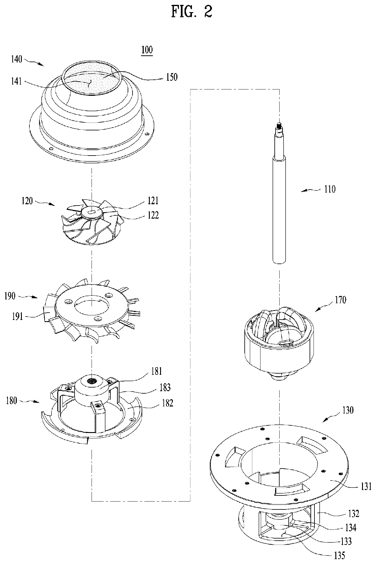
An embodiment of the present disclosure discloses a motor assembly including a rotation shaft, an impeller including a hub fastened to the rotation shaft, and a plurality of blades protruding outward from an outer surface of the hub, an inlet body for surrounding an outer circumference of the impeller, and a coating layer coated on an inner surface of the inlet body, wherein at least a portion of the coating layer is ground in a form of powder by friction with the plurality of blades during rotation of the impeller.

Description

CROSS-REFERENCE TO RELATED APPLICATIONS[0001]This application claims the benefit of Korean Patent Application No. 10-2019-0069367, filed on Jun. 12, 2019, which is hereby incorporated by reference as when fully set forth herein.BACKGROUNDField[0002]Embodiments of the present disclosure relate to a motor assembly and a method for manufacturing the same, and more particularly, to a motor assembly having an inlet body surrounding an outer circumference of an impeller and a method for manufacturing the same.Discussion of the Related Art[0003]A motor may be installed in a household appliance, such as a cleaner, a hair dryer, or the like, a vehicle, and the like to function as a driving source for generating a rotational force. The motor may be coupled to a fan, and in this case, the rotational force of the motor is transmitted to the fan to generate airflow based on rotation of the fan. For example, when the motor is installed in the cleaner, the motor may rotate together with the fan to...

Claims


Application Information

Patent Timeline
Patent Type & Authority Applications(United States)
IPC IPC(8): F04D29/02F04D25/08
CPCF04D29/444F04D29/023F05B2280/6011F04D25/08F04D19/002F04D29/162F04D29/4253F04D25/082F04D29/5806F04D29/622F04D29/441F05D2300/611F04D17/08
Inventor HWANG, EUNJIKIM, BYUNGJIKKIM, SUNGGIHWANG, JISU
Owner LG ELECTRONICS INC
Learn More