Zipper bridge

a technology of zipper bridge and frac equipment, which is applied in the direction of process and machine control, wellbore/well accessories, instruments, etc., can solve the problems of uneven or increased stress on the connection of frac equipment, less safe and difficult work environment for operating and maintaining frac equipment, and difficult installation

Active Publication Date: 2020-12-17
OIL STATES ENERGY SERVICES
View PDF0 Cites 106 Cited by
  • Summary
  • Abstract
  • Description
  • Claims
  • Application Information

AI Technical Summary

Problems solved by technology

In particular, typically treatment fluid in the zipper manifold passes to frac trees via goat heads or frac heads and frac iron, but there are several drawbacks to using such setups to span the distance between the zipper manifold and each frac tree.
Goat heads, or frac heads, traditionally employ multiple downlines and restraints that clutter the area between the zipper manifold and the frac tree, which can make for a more difficult and less safe work environment to operate and maintain the frac equipment.
One drawback of this design is that the weight of the equipment combined with the potentially awkward orientation of the lines can make installation difficult and can place uneven or increased stress on the connections to the frac manifold and / or the frac tree.
Another drawback is that using a single line to connect the frac manifold to the frac tree can lead to increased velocity and turbulence of the flow, when compared to using multiple lines.
Such conditions may lead to a greater risk of erosion in the frac tree.
Replacing a damaged frac tree can be very expensive and time-consuming.

Method used


Image

  • Zipper bridge
  • Zipper bridge
  • Zipper bridge

Examples


Embodiment Construction

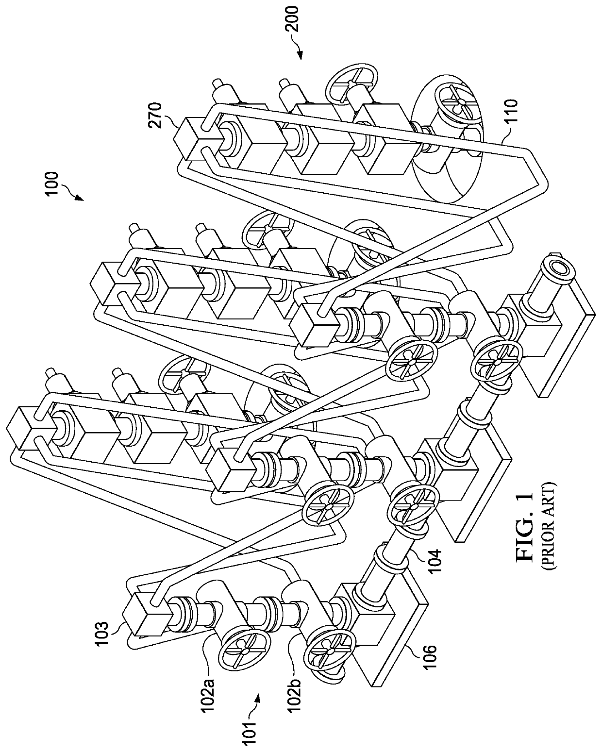
[0016]FIG. 1 illustrates an example of a prior art zipper manifold 100. The manifold may be positioned vertically, as shown in FIG. 1, or it may be positioned horizontally. The frac manifold 100 can include two or more well configuration units 101. Each well configuration unit 101 includes one or more valves 102 and a connection header 103, and the well configuration units 101 may be collectively or individually (as shown) positioned on skids 106. Each connection header 103 connects to a similar header on the frac tree. Prior art connection headers 103 are often called frac heads or goat heads and include multiple fluid connection points, as shown in FIG. 1. Each fluid connection point attaches to a downline 110 that is routed to the ground before turning back up and connecting to a connection point on the frac tree header 270 of the frac tree 200. The use of downlines 110 allows operators to adjust for different distances between and relative locations of the frac manifold 100. The...


PUM


Abstract

A frac zipper manifold bridge connector comprises two bridge spools for connecting a well configuration unit of a frac zipper manifold to a frac tree of a wellhead. The connector comprises multiple connections involving threaded flanges, such that the orientation of the bridge spools may be adjusted to ensure that they are correctly aligned with the frac tree. The bridge connector further comprises one or more flow diverters to decrease turbulence and reduce erosion.

Description

TECHNICAL FIELD[0001]The present disclosure relates generally to oil or gas wellbore equipment, and, more particularly, to a connector bridge for a frac manifold.BACKGROUND[0002]Frac manifolds, also referred to herein as zipper manifolds, are designed to allow hydraulic fracturing operations on multiple wells using a single frac pump output source. Frac manifolds are positioned between the frac pump output and frac trees of individual wells. A frac manifold system receives fracturing fluid from the pump output and directs it to one of many frac trees. Fracturing fluid flow is traditionally controlled by operating valves to isolate output to a single tree for fracking operations.[0003]Frac zipper manifolds may be rigged up to frac trees before frac equipment arrives at the well site. Once onsite, the frac equipment need only be connected to the input of the frac manifold. Because individual frac trees do not need to be rigged up and down for each fracking stage and because the same f...

Claims


Application Information

Patent Timeline
Patent Type & Authority Applications(United States)
IPC IPC(8): F17D5/00G05D7/06E21B43/267
CPCG05D7/0641F17D5/00E21B43/267E21B43/2607
Inventor SIZEMORE, RICHARD BRIANMCGUIRE, BOBARTHERHOLT, DANNY L.CLAXTON, MICKEYMULLINS, BLAKEBEEDY, CHARLES
Owner OIL STATES ENERGY SERVICES
Why Eureka
Try Eureka