Dual Detector With Transverse Coils

a detector and transverse coil technology, applied in the direction of electromagnetic wave detection, protective material radiating elements, instruments, etc., can solve the problems of insufficient training of operators using these detectors, inability to hold the detector properly, and inability to detect objects properly, so as to reduce false alarms and improve sensitivity

Active Publication Date: 2020-12-17
MANNESCHI ALESSANDRO
View PDF6 Cites 6 Cited by
  • Summary
  • Abstract
  • Description
  • Claims
  • Application Information

AI Technical Summary

Benefits of technology

[0007]An object of the invention is therefore to propose a dual detector comprising a detection head housing an inductive sensor and another sensor, such as a ground-penetrating radar, which is capable of reducing the false alarms likely to be generated during the scanning of a ground with the detector while having higher sensitivity

Problems solved by technology

In use, the Applicant has however noticed that the ground was not neutral from an electromagnetic point of view and can therefore disturb the coupling between the windings.
In addition, the ground is rarely uniformly magnetic so that, during the scanning of the ground with the detector by an operator, the detected signal can vary only due to the presence of metal debris or to the very composition of the ground, or even trigger false alarms.
In addition, the operators using these detectors may be inadequately trained and may not hold the detector properly or perform an inappropriate scanning motion.
The detection head can then form a lateral angle with the ground, so that one of the coils is closer to the ground than the other of the coils, which creates a strong modulation of the signal and therefore risks triggering false alarms.
And even if the operator were well trained and tried to keep the detection head substantially parallel to the ground at any point in the scanning motion, he cannot locally modify its inclination to take into account the unevenness in the ground.
In order to overcome these difficulties, manufacturers tend to reduce the sensitivity of these detectors.
The risk, however, is that it will no longer be able to detect targets buried in the ground and therefore put the lives of the operators in danger.

Method used


Image

  • Dual Detector With Transverse Coils
  • Dual Detector With Transverse Coils
  • Dual Detector With Transverse Coils

Examples


Embodiment Construction

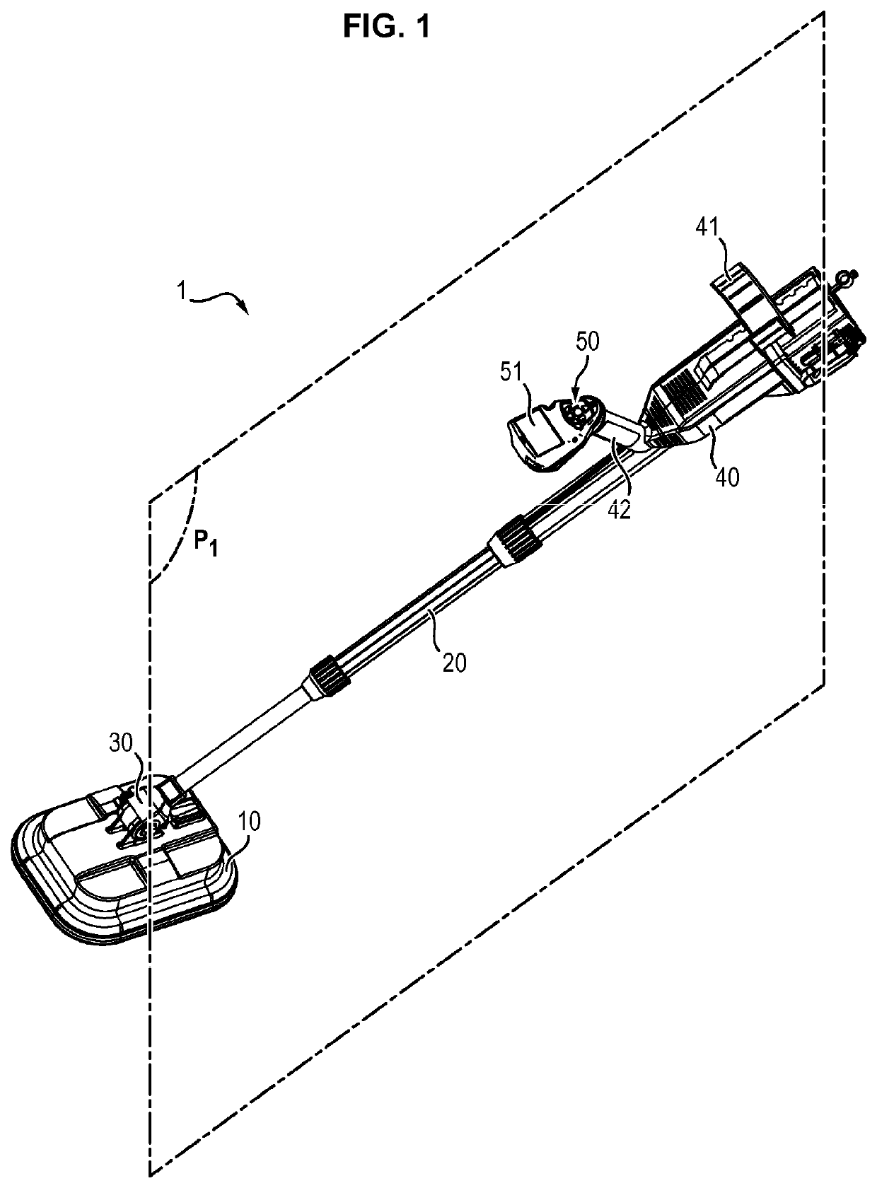
[0027]A dual detector 1 according to the invention comprises a detection head 10.

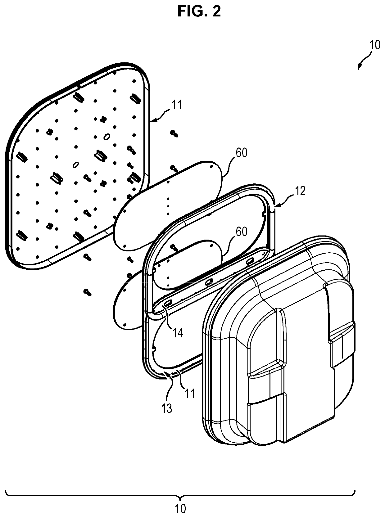
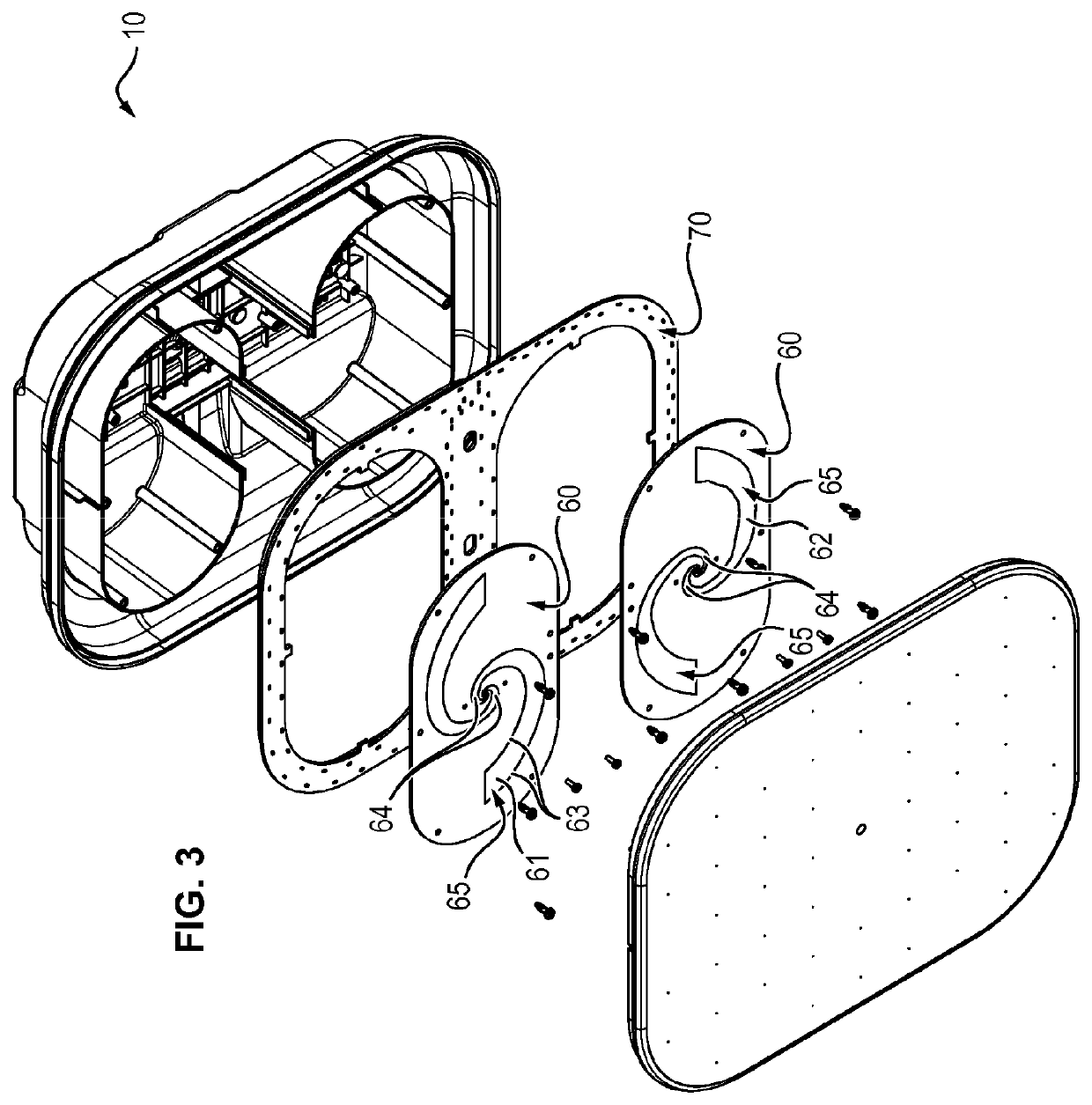
[0028]The detection head 10 corresponds to the part intended to come close to the ground in order to detect target products. To this end, it comprises:[0029]an inductive sensor 12, 13, and[0030]a ground-penetrating radar 60 comprising a transmitting antenna 61 and a receiving antenna 62.

[0031]The inductive sensor 12, 13 comprises either a single coil forming the transmitter and the receiver, or a transmitting coil 12 and a receiving coil 13, which are distinct from each other. The transmitting coil 12 and the receiving coil then each form a loop and are shaped so that the loop of the transmitting coil 12 at least partially overlaps the loop of the receiving coil 13 so as to form a coupling area 14. This configuration allows obtaining an inductive sensor in which the mutual inductance is minimal.

[0032]By way of comparison, compared to an inductive sensor comprising a single coil constituting the transmit...


PUM


Abstract

The invention relates to a dual detector comprising a detection head having: an inductive sensor which is mounted on the platform (11) and includes a transmitter coil (12) and a separate receiver coil (13), the transmitter coil (12) and the receiver coil (13) each forming a loop, a soil penetrating radar (60) comprising a transmitter antenna (61) and a receiver antenna (62), the transmitter antenna (61) and the receiver antenna (62) each being accommodated in the center of one of the loops of the transmitter and receiver coils (12) (13), the transmitter antenna (61) and the receiver antenna (62) having a maximum thickness (e) of one micron in order to limit interference with the inductive sensor (12).

Description

FIELD OF THE INVENTION[0001]The invention relates to the field of the detection of target objects, and more particularly to the detection of explosive charges such as landmines buried in the ground.TECHNOLOGICAL BACKGROUND[0002]In order to detect explosive charges, it is known to use dual technology detectors (“dual detectors”) comprising a detection head housing an inductive sensor and a ground-penetrating radar, insofar as these technologies are complementary as for the types of detected materials (metals for the inductive sensor vs. differences in dielectric constants of the materials and relative position for the radar).[0003]In use, the Applicant has however noticed that the ground was not neutral from an electromagnetic point of view and can therefore disturb the coupling between the windings. In addition, the ground is rarely uniformly magnetic so that, during the scanning of the ground with the detector by an operator, the detected signal can vary only due to the presence of...

Claims


Application Information

Patent Timeline
Patent Type & Authority Applications(United States)
IPC IPC(8): G01S13/88G01V3/12G01V3/10H01Q1/40
CPCG01S13/885H01Q1/40G01V3/10G01V3/12G01S13/887F41H11/136H04B5/0043H04B5/0075G01V3/16G01V3/15H04B5/00
Inventor MANNESCHI, ALESSANDRO
Owner MANNESCHI ALESSANDRO
Why Eureka
Try Eureka