Monitor device provided with camera for capturing motion image of motion of robot device

Active Publication Date: 2020-12-24
FANUC LTD
View PDF0 Cites 1 Cited by
  • Summary
  • Abstract
  • Description
  • Claims
  • Application Information

AI Technical Summary

Benefits of technology

The present patent is for a device that monitors the motion of a robot device with a camera and a status detector. The device can detect abnormal vibrations or operational failure of the robot device and capture the corresponding motion images. The device can also identify the cause of the abnormality by analyzing the motion images and recording of the robot device operations. This helps in quickly identifying and addressing the issues with the robot device, reducing the downtime for maintenance.

Problems solved by technology

In this case, the workpiece placed on the vehicle may vibrate due to an uneven ground surface or an air flow in a factory.
As a result, when an operation tool comes into contact with the workpiece, the robot device may detect vibrations and stop.
Alternatively, in the event of a failure of a device included in the robot device, a robot may largely vibrate and the robot device stops.
Thus, the analysis of the cause is a time-consuming work for the operator.
However, a correspondence between an operation record of the robot device and a time in a motion image cannot be identified.
Since information on a correspondence between an operation record of the robot device and a time in a motion image is not provided, it is difficult to analyze the cause of an abnormality with reference to the motion image and the operation record of the robot at the occurrence of the abnormality.
Hence, in the related art, it is difficult to analyze the cause of an abnormality in a short time, resulting in a long recovery time for the robot device.

Method used


Image

  • Monitor device provided with camera for capturing motion image of motion of robot device
  • Monitor device provided with camera for capturing motion image of motion of robot device
  • Monitor device provided with camera for capturing motion image of motion of robot device

Examples


Embodiment Construction

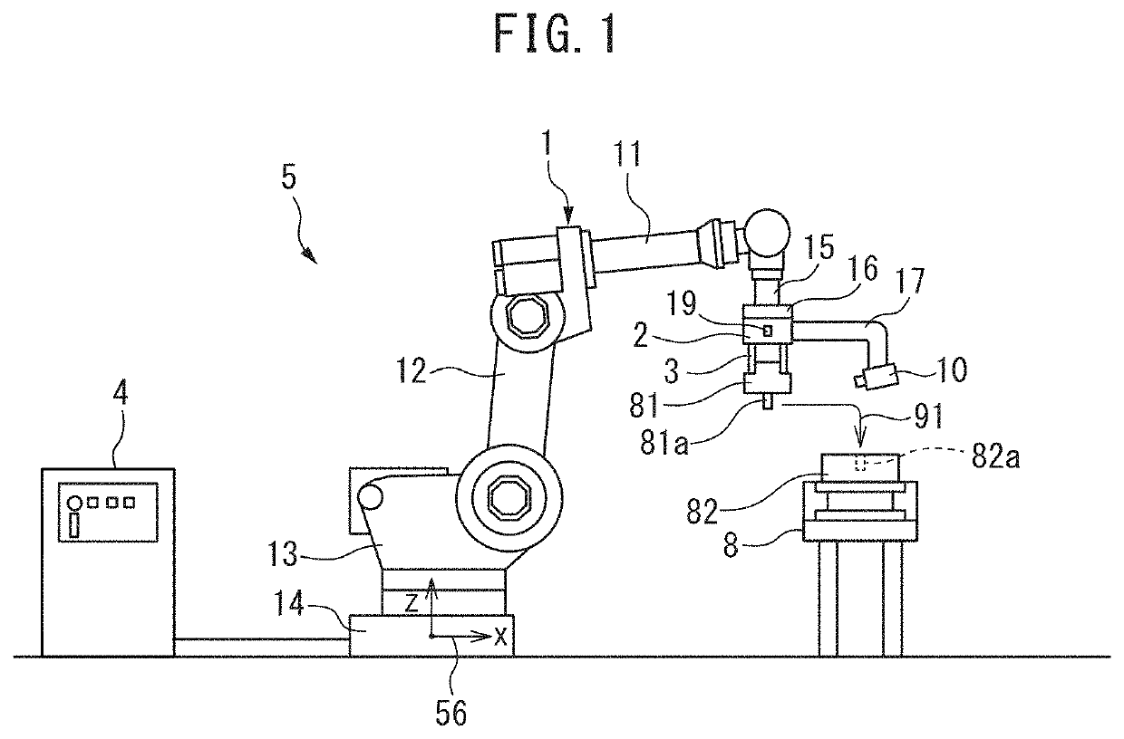
[0016]Referring to FIGS. 1 to 7, a monitor device that monitors a motion of a robot device according to an embodiment will be described below. In the present embodiment, the robot device for assembling parts will be described as an example.

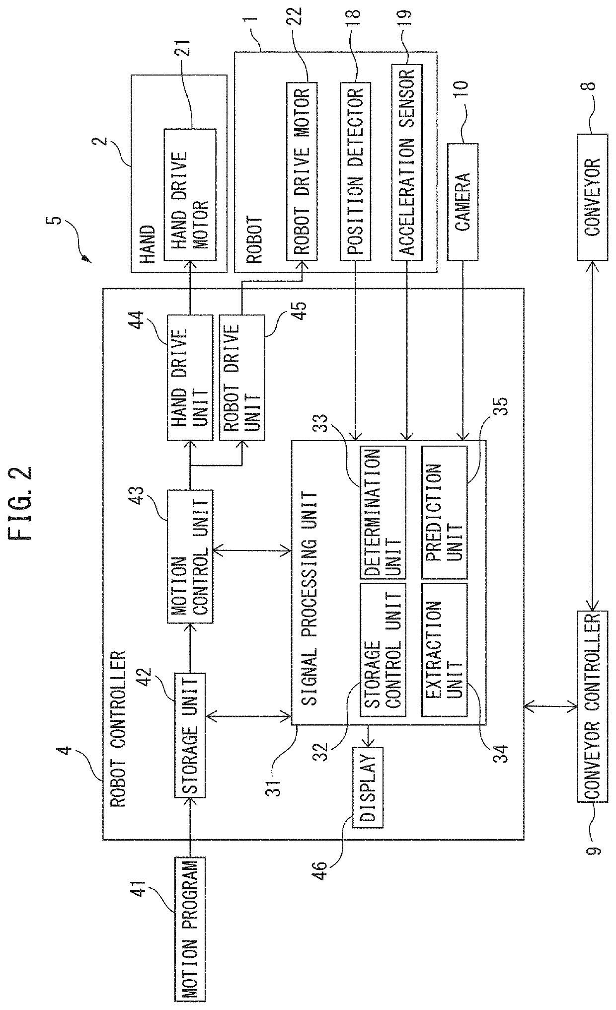
[0017]FIG. 1 is a schematic diagram of a first robot device according to the present embodiment. A first robot device 5 includes a hand 2 acting as an operation tool (end effector) and a robot 1 that moves the hand 2. The robot 1 of the present embodiment is an articulated robot including a plurality of joints.

[0018]The robot 1 includes a base part 14 and a rotation base 13 supported by the base part 14. The base part 14 is fixed to an installation surface. The rotation base 13 is formed so as to rotate relative to the base part 14. The robot 1 includes an upper arm 11 and a lower arm 12. The lower arm 12 is pivotally supported by the rotation base 13 via the joint. The upper arm 11 is pivotally supported by the lower arm 12 via the joint. The upp...


PUM


Abstract

A monitor device includes a camera for capturing a motion image of a motion of a robot device and an acceleration sensor for detecting an operational status of the robot device. A storage control unit for a robot controller performs control for storing, in a storage unit, a motion image captured by the camera and attached with a time, and control for storing, in the storage unit, an acceleration acquired from an acceleration sensor and attached with a time. When the operational status of the robot device deviates from a reference operational status, an extraction unit extracts, from the storage unit, a motion image in a period preceding the deviation from the reference operational status and stores the extracted motion image in the storage unit.

Description

BACKGROUND OF THE INVENTION1. Field of the Invention[0001]The present invention relates to a monitor device provided with a camera for capturing a motion image of a motion of a robot device.2. Description of the Related Art[0002]In a robot device including a robot, a desired operation can be performed by attaching an operation tool corresponding to the operation to the robot. For example, the operation tool may be a hand attached to the robot so as to grip a workpiece. After the robot reaches a predetermined position and posture, a workpiece can be transferred by the hand that holds or releases the workpiece.[0003]The robot and the operation tool are driven based on a created motion program. However, the operation of the robot device may not be normally performed depending upon the occurrence of an abnormality or a status around the robot device being driven. A camera may be disposed in the robot device in order to identify a status of the robot device or a status around the robot d...

Claims


Application Information

Patent Timeline
IPC IPC(8): G06K9/00G06T7/20H04N7/18H04N5/76
CPCH04N5/76G06T7/20G06K9/00664H04N7/18B25J9/1674B25J9/161B25J19/04G06T7/001G06T7/246G06T2207/30164G06T2207/30241G06T2207/30244H04N5/772H04N7/183G06V20/10
Inventor OOBA, MASAFUMI
Owner FANUC LTD
Why Eureka
Try Eureka