Synchronization control device
a control device and synchronization technology, applied in the direction of dynamo-electric motor control, control using feedback, instruments, etc., can solve the problems of synchronous deviation and the inability to develop a technique to suppress synchronous deviation, and achieve good track followability
- Summary
- Abstract
- Description
- Claims
- Application Information
AI Technical Summary
Benefits of technology
Problems solved by technology
Method used
Image
Examples
application example
[0032]An application example of the present invention will be described first.
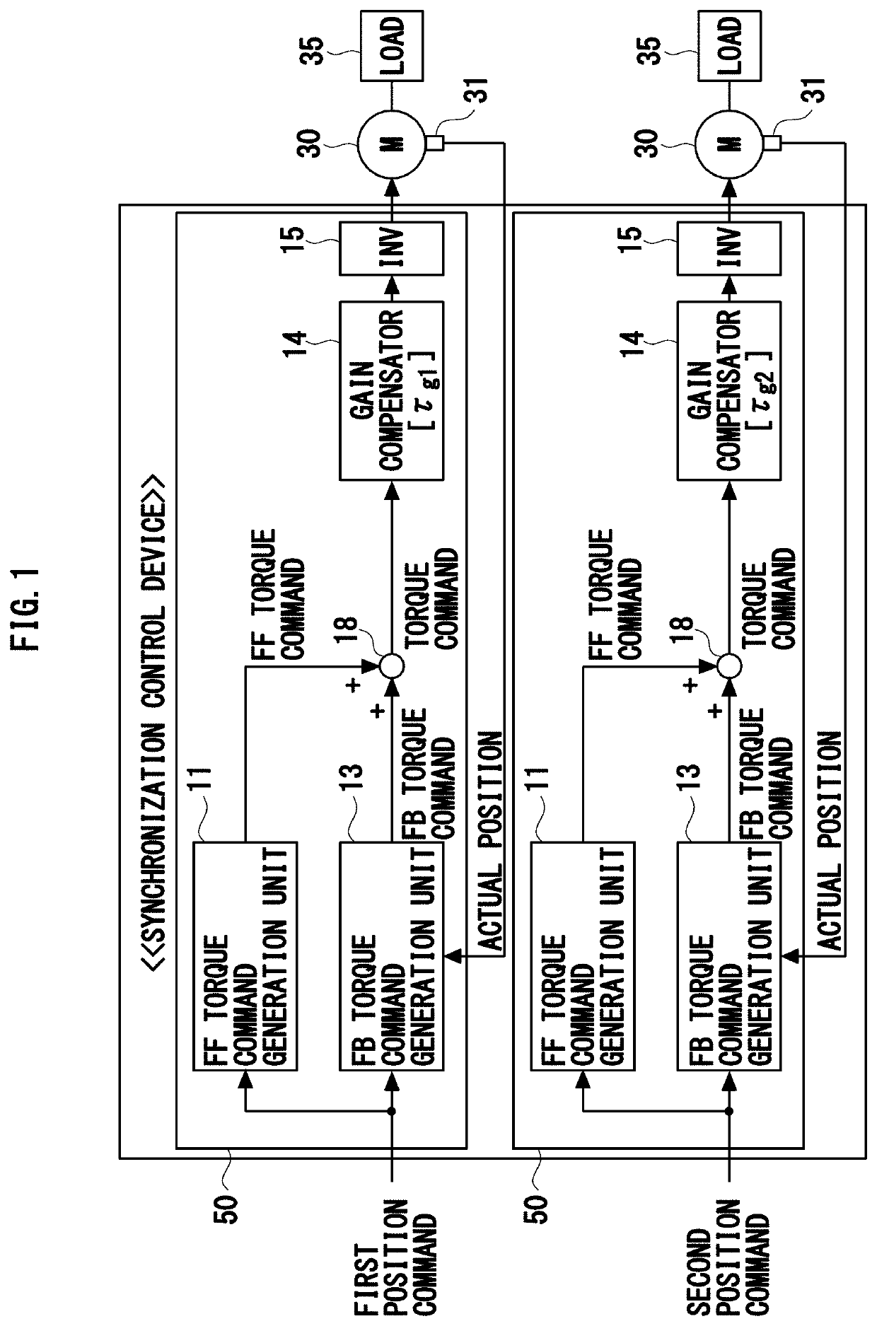
[0033]The present invention is applied to a synchronization control device having a configuration illustrated in FIG. 1.
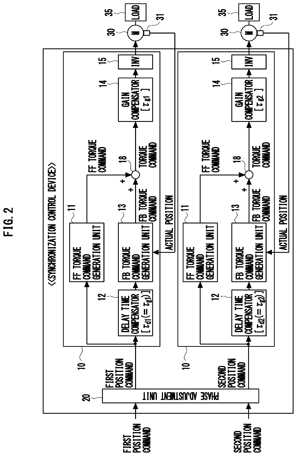
[0034]This synchronization control device is a device that synchronously controls two shafts (two motors 30 to which a load 35 is connected). The synchronization control device includes a control unit 50 which controls a first motor 30 on the basis of a first position command, and a control unit 50 which controls a second motor 30 on the basis of a second position command. In FIG. 1, each position command is input to the control unit 50 from outside the synchronization control device, but each position command may be generated within the synchronization control device. Hereafter a control unit 50, that controls an n-th motor 30 on the basis of an n-th (n=1, 2) position command, is called an n-th control unit 50. Further, each unit (e.g. FF torque command generation unit 11) in the n-th co...
embodiment 1
[0044]FIG. 4 indicates a general configuration of a synchronization control device 1 according to Embodiment 1 of the present invention. The configurations of the FF torque command generation unit 11 and the FB torque command generation unit 13 illustrated in FIG. 4 are commonly used. Hence, a detailed description on each command generation unit is omitted. J1 and J2 indicate the inertia of the mechanical system (motor 30 and load 35), Kpp indicates a position loop gain, Kvp indicates a velocity loop gain, Ki indicates an integration gain, and s is a Laplace operator.
[0045]As illustrated in FIG. 4, the synchronization control device 1 according to Embodiment 1 is a device where the first gain compensator 14 is a notch filter NF1 of which central frequency ω1 is 200 Hz, and the second gain compensator 14 is a notch filter NF2 of which central frequency ω2 is 1000 Hz. Hereafter the equivalent time constant of the notch filter NFn (n=1, 2) is written as τnfn.
[0046]In the synchronizatio...
embodiment 2
[0055]FIG. 6 indicates a general configuration of a synchronization control device 2 according to Embodiment 2 of the present invention.
[0056]As illustrated in FIG. 6, the synchronization control device 2 according to Embodiment 2 is a device where a notch filter NF1, of which central frequency ω1 is 200 Hz, is used for the first gain compensator 14, and a notch filter NF2, of which central frequency ω2 is 1,000 Hz, is used for the second gain compensator 14, as in the case of the synchronization control device 1.
[0057]In the synchronization control device 2, however, not the notch filter NF1 but a low-pass filter LPF1, of which equivalent time constant τp1 is the same as the equivalent time constant Tnf1 of the notch filter NF1 (first gain compensator 14), is used for the first delay time compensator 12. Further, in the synchronization control device 2, not the notch filter NF2 but a low-pass filter LPF2, of which equivalent time constant τp2 is the same as the equivalent time cons...
PUM
 Abstract
Description
Claims
Application Information
 - R&D
- Intellectual Property
- Life Sciences
- Materials
- Tech Scout
- Unparalleled Data Quality
- Higher Quality Content
- 60% Fewer Hallucinations
Browse by: Latest US Patents, China's latest patents, Technical Efficacy Thesaurus, Application Domain, Technology Topic, Popular Technical Reports.
© 2025 PatSnap. All rights reserved.Legal|Privacy policy|Modern Slavery Act Transparency Statement|Sitemap|About US| Contact US: help@patsnap.com


