
Controlling myopia in humans

a technology of artificial light source and control light source, which is applied in the field of artificial light source for controlling myopia in humans, can solve the problems of putting pressure on health costs for both developed and developing nations, and high risk of ocular morbidity in older age, and achieve the effect of reducing the onset or progression of myopia

Inactive Publication Date: 2021-01-07
SUSTAINABLE EYE HEALTH IP PTY LTD
View PDF0 Cites 3 Cited by
  • Summary
  • Abstract
  • Description
  • Claims
  • Application Information

AI Technical Summary

Benefits of technology

The patent describes a method for using electronic control modules to expose individuals' eyes to artificial light to prevent or reduce the development of myopia (nearsightedness). The artificial light is designed to mimic the natural light that the eyes are exposed to when outside, but with specific wavelengths that trigger a neurological response in the retina, leading to a reduction in the onset or progression of myopia. The exposure to the artificial light should last at least 180 minutes per day and at least 1,800 lux-hours per day. The patent also describes the wavelength of light that triggers this response, which is important for maintaining the proper function and structure of the eye. Overall, the patent provides a technical solution for preventing or reducing the risk of myopia in young individuals.

Problems solved by technology

Of these, 10% are likely to be highly myopic (more than −5.00 Dioptres) leading to a high risk of ocular morbidity in older age.
This is destined to place pressure on health costs for both developed and developing nations globally.

Method used


Image

  • Controlling myopia in humans
  • Controlling myopia in humans
  • Controlling myopia in humans

Examples


Embodiment Construction

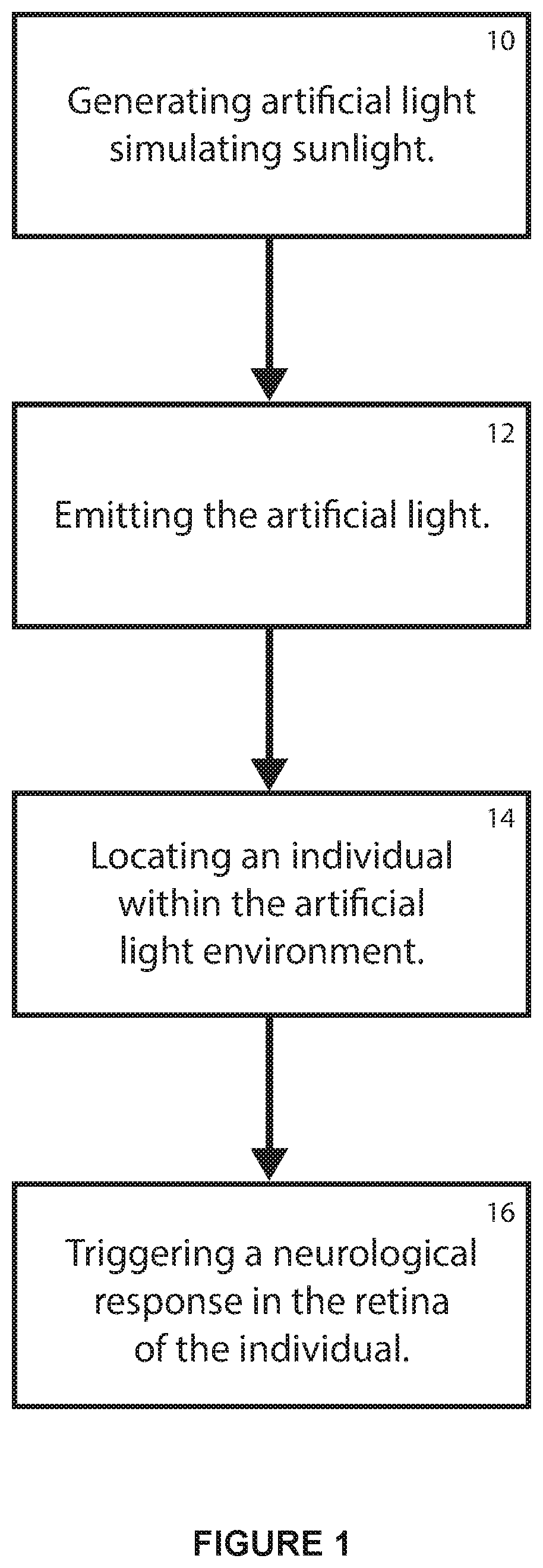
[0039]In the flowchart of FIG. 1 the general steps involved in exposing an individual's eyes to artificial light to control myopia include:[0040]1. generating the artificial light which substantially simulates the effect on the eyes of sunlight at 10;[0041]2. emitting the artificial light at a predetermined level of illuminance for a predetermined exposure period of time at 12;[0042]3. locating the individual's eyes within the environment in which the artificial light is emitted at 14 for the predetermined exposure period;[0043]4. triggering a neurological response at a local level in the retina of each of the eyes which is effective in contributing to a reduction in the onset or progression of myopia in the individual's eyes at 16.

[0044]In this embodiment the individual's eyes are exposed to the artificial light which is emitted within an indoor environment occupied by the individual. The indoor environment may be in the form of a classroom occupied by children and the artificial l...


PUM

PropertyMeasurementUnit
illuminanceaaaaaaaaaa
wavelengthsaaaaaaaaaa

Abstract

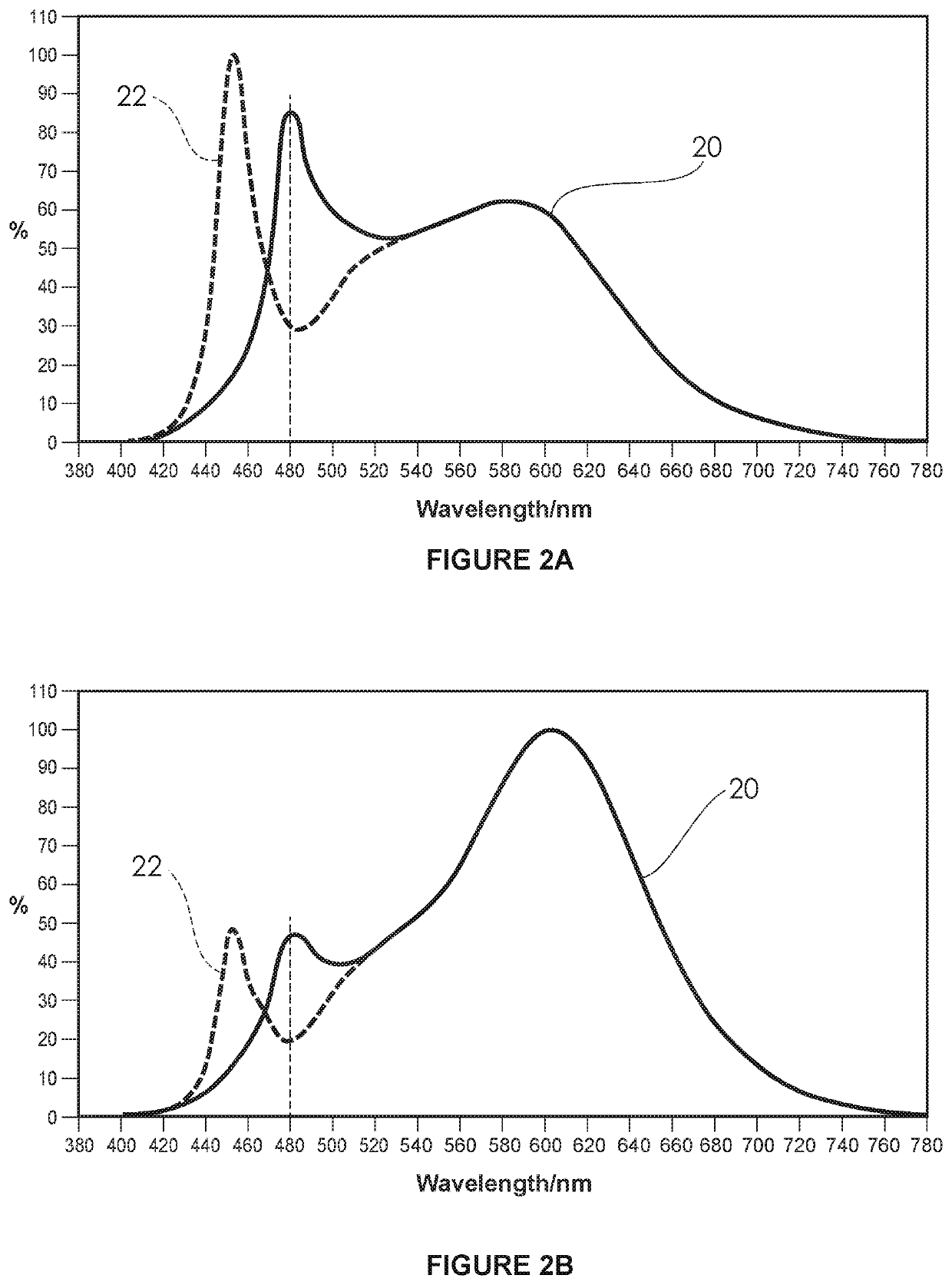
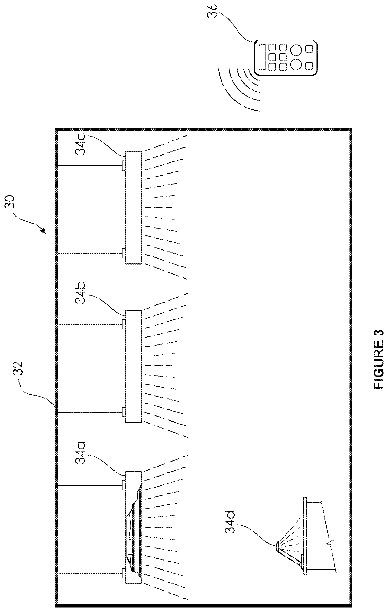
The present invention is broadly directed to an artificial lighting system 30 for emitting artificial light in an indoor environment for controlling myopia in humans. The artificial lighting system 30 generally comprises:1. one or more luminaires such as 34a to 34d designed to directly generate and emit artificial light without filters which substantially simulates the effect of sunlight and is of a predetermined wavelength emission spectrum (a) higher in its proportion of wavelengths at or around 480 nm relatively to neighbouring wavelengths, and (b) lower in its proportion of high energy visible light;2. an electronic control module 36 operatively coupled to the luminaires such as 34a to control their emission of the artificial light.

Description

TECHNICAL FIELD[0001]The present invention relates broadly to an artificial light source for controlling myopia in humans and relates particularly, although not exclusively, to an artificial lighting system and method for emitting artificial light suitable for controlling myopia in humans.BACKGROUND OF INVENTION[0002]Myopia or short-sightedness is reaching epidemic levels where for example it is estimated that half of young adults in the US and Europe and up to 90% of teenagers and young adults in China are myopic. It is also estimated that by 2020 around one third of the world's population could be short-sighted and by 2050 half of the world's population will be short-sighted. Of these, 10% are likely to be highly myopic (more than −5.00 Dioptres) leading to a high risk of ocular morbidity in older age. This is destined to place pressure on health costs for both developed and developing nations globally. It is understood that myopia is most commonly a consequence of an axial elonga...

Claims


Application Information

Patent Timeline
Patent Type & Authority Applications(United States)
IPC IPC(8): A61N5/06H05B45/20H05B45/10H05B44/00
CPCA61N5/0613H05B45/20A61N2005/0663A61N2005/0632A61N2005/0652H05B45/10A61N5/0622A61F9/00A61N2005/065A61N2005/0651A61M2021/0044A61N5/0618A61N2005/0626A61N2005/0628A61N2005/0662H01L33/08H01L33/507H01L27/15F21Y2115/10H05B33/02H01L33/02F21S8/04F21S6/002F21V9/02A61N2005/0654A61N2005/0665A61N2005/0642H05B47/19H05B44/00A61F9/0079H05B45/22F21Y2115/20F21Y2113/10Y02B20/30Y02B20/40
Inventor MASON, STEPHEN
Owner SUSTAINABLE EYE HEALTH IP PTY LTD
Learn More