Mounting method of a rotor assembly comprising a bearing into a frame comprising adhesive

a technology of rotor assembly and adhesive, which is applied in the direction of dynamo-electric machines, electrical apparatus, magnetic circuit rotating parts, etc., can solve the problems of preventing the bearing from functioning completely, the adhesive flow between the bearing and the bearing seat in an uncontrolled manner, etc., and achieves short cure time, long cure time, the effect of short cure tim

Inactive Publication Date: 2021-01-07
DYSON TECH LTD
View PDF0 Cites 1 Cited by
  • Summary
  • Abstract
  • Description
  • Claims
  • Application Information

AI Technical Summary

Benefits of technology

[0006]In particular, injecting an adhesive through the aperture into the annular groove may allow for the adhesive to be applied post-location of the bearing in the bearing seat. This may allow for a cleaner application of adhesive, and may reduce the risk of adhesive contaminating other components during application, compared to, for example, applying the adhesive pre-location of the bearing in the bearing seat.
[0021]The bearing may comprise a further groove, and the further groove may be exposed through the cut-out. The method may comprise applying tacking adhesive to the further groove. This may be beneficial as the further groove may provide a mechanical key, which may provide the tacking adhesive bond with sufficient strength to perform its function of retaining the bearing and bearing seat in position during curing of the adhesive applied through the aperture.

Problems solved by technology

Furthermore, utilising an annular groove may reduce the chance that adhesive will flow out from between the bearing and the bearing seat in an uncontrolled manner during application of the adhesive.
If adhesive is able to flow at the interface between the bearing and the bearing seat in an uncontrolled manner, there is the chance that the adhesive may enter into the bearing itself, which may be extremely detrimental to the bearing and may stop the bearing from functioning completely.

Method used


Image

  • Mounting method of a rotor assembly comprising a bearing into a frame comprising adhesive
  • Mounting method of a rotor assembly comprising a bearing into a frame comprising adhesive
  • Mounting method of a rotor assembly comprising a bearing into a frame comprising adhesive

Examples


first embodiment

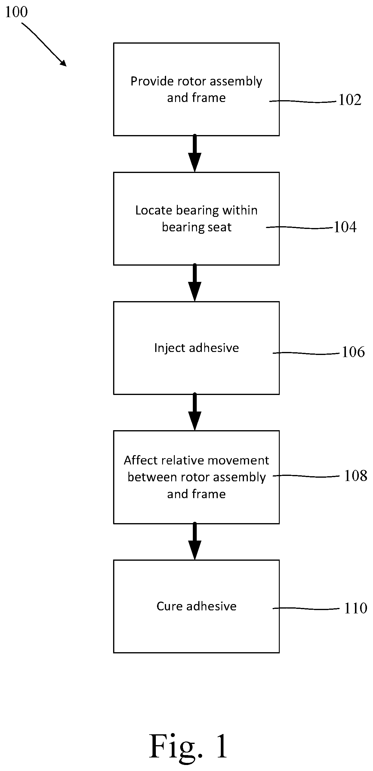
[0038]a method, generally designated 100, of mounting a rotor assembly 12 to a frame 14 of an electric motor 10, is shown in the block diagram of FIG. 1.

[0039]The method 100 comprises an initial step 102 of providing a rotor assembly 12 having a bearing 26 and a frame 14 having a bearing seat 44. A suitable rotor assembly 12 is shown in isolation in FIG. 6, whilst a suitable frame 14 is shown in isolation in FIG. 7.

[0040]The rotor assembly 12 comprises a shaft 16 on which is mounted a rotor core permanent magnet 18, a first balancing ring 20, a second balancing ring 22, and first 24 and second 26 bearings mounted on the shaft 16 on either side of the rotor core permanent magnet 18 and balancing rings 20, 22. An impeller 28 is mounted at one end of the shaft 16, and a sensor magnet 30 is mounted at the other end.

[0041]Although not shown in FIG. 6, the first bearing 24 is provided with annular grooves on the outer circumferential surface thereof. O-rings 32 sit within the annular groo...

second embodiment

[0055]a method, generally designated 200, of mounting a rotor assembly 12 to a frame 14 of an electric motor 10, is shown schematically in FIG. 11.

[0056]The second embodiment of the method 200 is substantially the same as the first embodiment of the method 100, but comprises the additional steps of applying 202 a second adhesive 37 at the cut-out 50, and curing 204 the second adhesive 37 before curing 110 the first adhesive 35.

[0057]Following relative movement between the second bearing 26 and the second bearing seat 44, the second annular groove 36 of the second bearing 26 is exposed through the cut-out 50 in the second bearing seat 44. The second adhesive 37 is applied at the cut-out 50 such that the second adhesive 37 covers at least a portion of the second bearing seat 44 and flows into the second annular groove 36.

[0058]The second adhesive 37 is a quick UV curing adhesive, and in a presently preferred embodiment is the adhesive known as Loctite® 3556 available from Henkel Locti...


PUM


Abstract

A method of mounting a rotor assembly to a frame of an electric motor. The method includes providing a rotor assembly having a bearing and a frame having a bearing seat. The bearing seat has an aperture. The bearing and / or the internal surface of the bearing seat has an annular groove. The method includes locating the bearing within the bearing seat. The method includes injecting an adhesive through the aperture into the annular groove. The method includes affecting relative movement between the bearing and the bearing seat. The method includes curing the adhesive.

Description

REFERENCE TO RELATED APPLICATIONS[0001]This application is a national stage application under 35 USC 371 of International Application No. PCT / GB2019 / 050451, filed Feb. 19, 2019, which claims the priority of United Kingdom Application No. 1803351.4 filed Mar. 1, 2018, the entire contents of each of which are incorporated herein by reference.FIELD OF THE DISCLOSURE[0002]The present disclosure relates to a method of mounting a rotor assembly to a frame of an electric motor, and to an electric motor.BACKGROUND OF THE DISCLOSURE[0003]There is a general desire to improve electric machines, such as brushless electric motors, in a number of ways. In particular, improvements may be desired in terms of size, weight, manufacturing cost, efficiency, reliability and noise.SUMMARY OF THE DISCLOSURE[0004]According to a first aspect of the present invention there is provided a method of mounting a rotor assembly to a frame of an electric motor, the method comprising providing a rotor assembly havin...

Claims


Application Information

Patent Timeline
Patent Type & Authority Applications(United States)
IPC IPC(8): H02K5/173H02K7/04H02K7/08H02K7/14H02K15/14H02K11/215H02K21/14
CPCH02K5/1732H02K7/04H02K7/083H02K21/14H02K15/14H02K11/215H02K7/14H02K1/28H02K5/161H02K15/16
Inventor IONS, DAVIDSTOTT, JOHN DECLANSTAFFORD, THOMAS RICHARD
Owner DYSON TECH LTD
Why Eureka
Try Eureka