
Cannula assembly with deployable camera

a technology of cannulas and cameras, applied in the field of cannula assemblies, can solve the problems of limiting the view provided by the camera to the longitudinal axis of the cannula, affecting the operation of the cannula, so as to achieve the effect of cleaning the surface and enhancing the effectiveness of the wiper assembly

Active Publication Date: 2021-01-14
NEW VIEW SURGICAL
View PDF0 Cites 0 Cited by
  • Summary
  • Abstract
  • Description
  • Claims
  • Application Information

AI Technical Summary

Benefits of technology

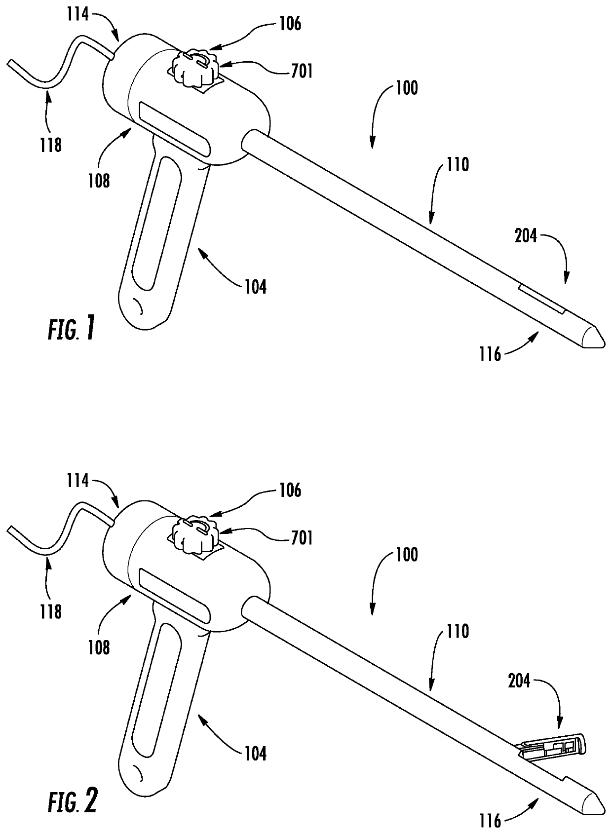
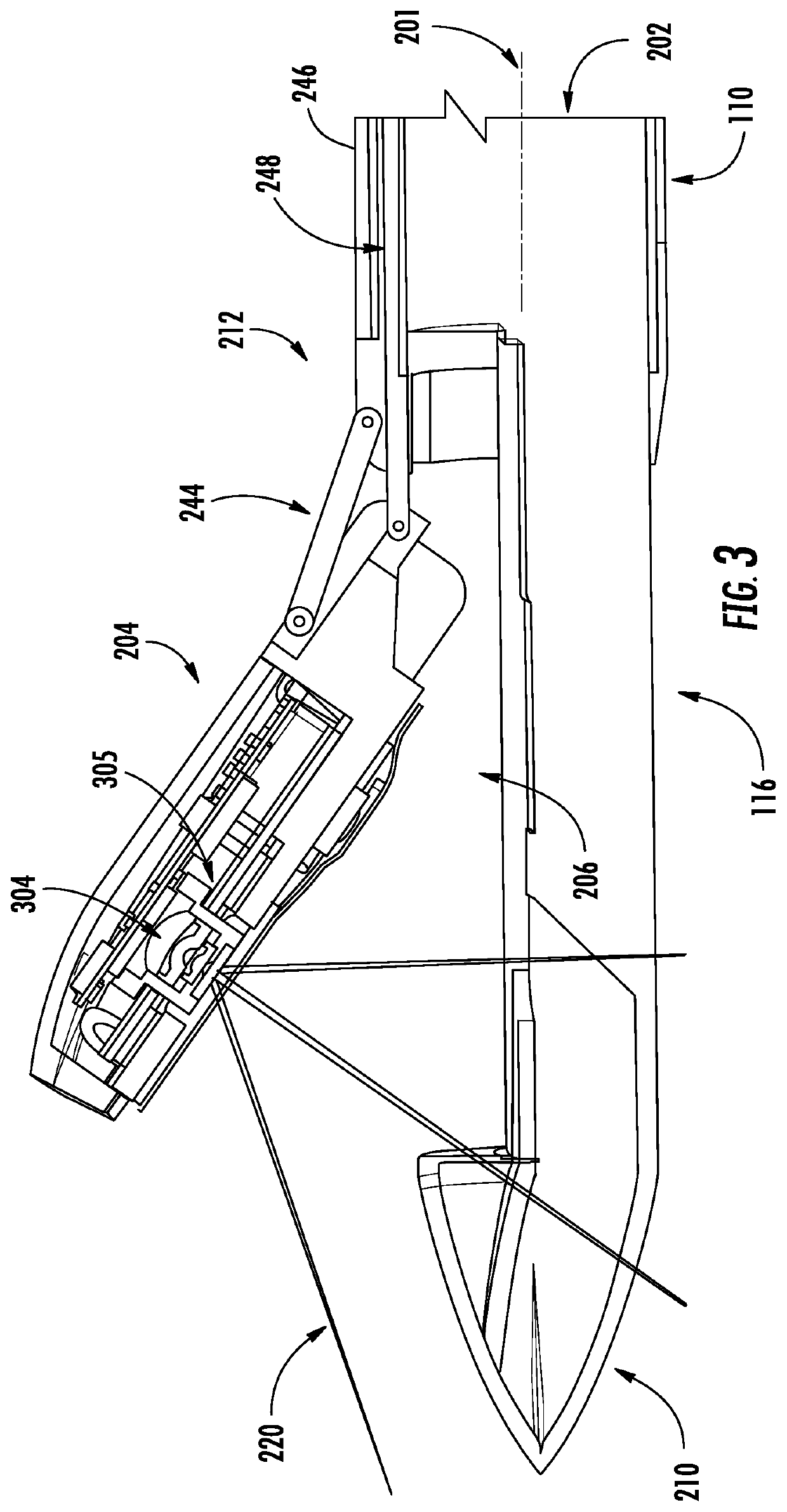
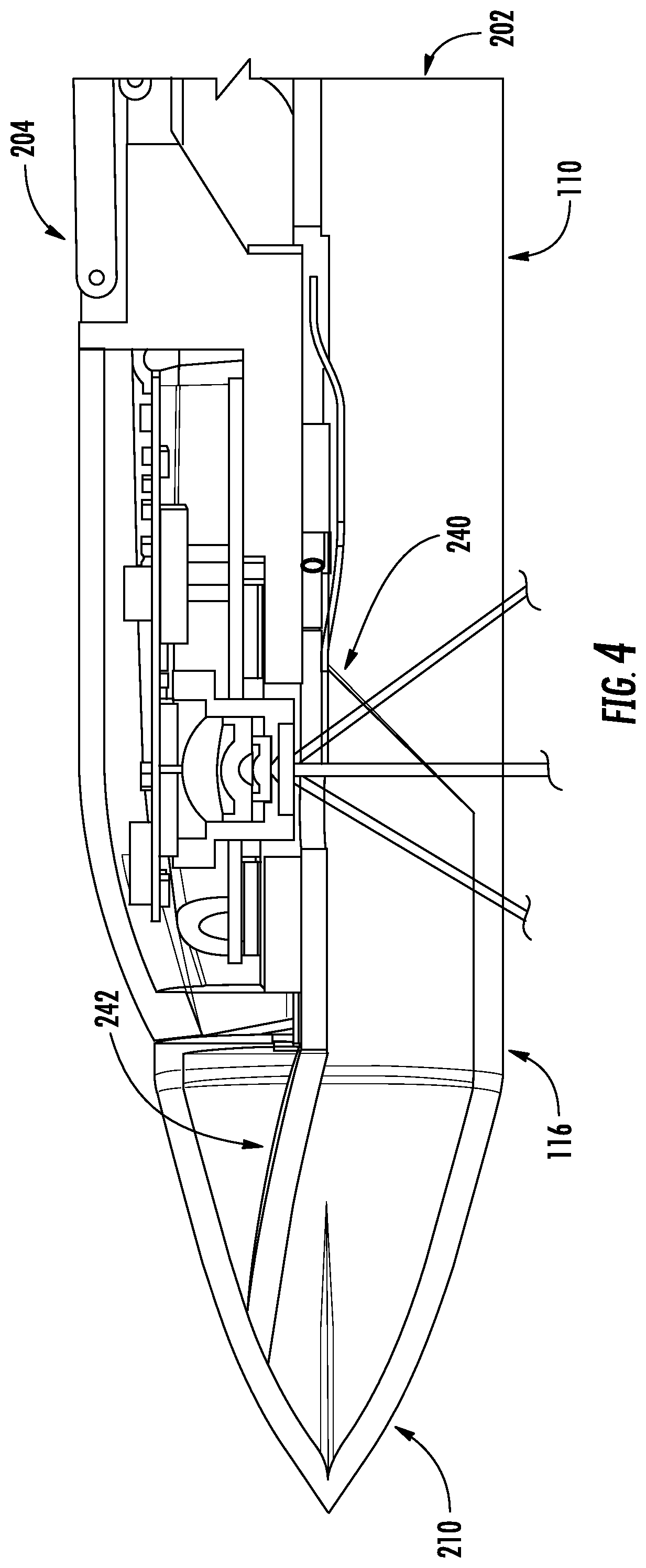
The present invention is a cannula assembly that combines the functions of a cannula, imaging, and illumination in a single device. The assembly has a housing that can be rotated between a closed position and one or more open positions. The housing contains an image transmission device and illumination components for providing light to the surgical site. The housing can be positioned distal to the proximal end of the tube to protect the electronic components while the tube is being used to pass through an incision in the patient. The cannula assembly also includes an irrigation assembly for flushing the camera lens with fluid prior to use. The invention makes it easier to control the access, imaging, and instrument use during minimally invasive surgery while using fewer incisions in the patient.

Problems solved by technology

In some cases, these devices comprise a camera mounted to the proximal end of the cannula, thereby limiting the view provided by the camera to the longitudinal axis of the cannula.
While this allows a broader view of the surgical area, it limits the design of the distal end of the cannula.
Moreover, the optics of the imaging and lighting components can be damaged during movement of the device within the body cavity or during insertion and / or removal of the device.
In particular, these designs expose the optics to potential damage when the distal end of the cannula is being used to create a percutaneous penetration or incision in the patient.

Method used


Image

  • Cannula assembly with deployable camera
  • Cannula assembly with deployable camera
  • Cannula assembly with deployable camera

Examples


Embodiment Construction

[0044]This description and the accompanying drawings illustrate exemplary embodiments and should not be taken as limiting, with the claims defining the scope of the present disclosure, including equivalents. Various mechanical, compositional, structural, and operational changes may be made without departing from the scope of this description and the claims, including equivalents. In some instances, well-known structures and techniques have not been shown or described in detail so as not to obscure the disclosure. Like numbers in two or more figures represent the same or similar elements. Furthermore, elements and their associated aspects that are described in detail with reference to one embodiment may, whenever practical, be included in other embodiments in which they are not specifically shown or described. For example, if an element is described in detail with reference to one embodiment and is not described with reference to a second embodiment, the element may nevertheless be c...


PUM


Abstract

The present disclosure provides a cannula assembly having a tube with an internal lumen, a proximal end portion and a distal end portion configured for insertion into a patient. The cannula assembly further includes a housing rotatably coupled to the tube between a closed position and one or more open positions. The housing contains an electronic component comprising an image transmission device, such as a camera, for collecting and receiving images of the surgical site. The housing is adapted to provide the image transmission device with a longitudinal or forward view when the housing is in the closed position and a transverse view (i.e., offset from the longitudinal axis) when the housing is in one of the open positions. The housing is disposed distal to the proximal end portion and proximal to the distal end portion of the tube to protect the image transmission device as the distal end portion creates an incision and / or passes through an existing incision in the patient.

Description

BACKGROUND OF THE INVENTION[0001]The field of the present disclosure relates generally to cannula assemblies with integrated imaging and illumination devices, and more particularly to cannulas with deployable cameras that provide a viewing angle offset from the cannula axis.[0002]In minimally invasive surgery, there are often several small incisions made into the body to insert surgical tools, insufflation devices, endoscopes or other viewing devices. Endoscopic surgical procedures performed through a tubular cannula have evolved over the years. Presently, surgeons are performing endoscopic procedures in any hollow viscus of the torso body area after the region has been insuffiated. Typically, multiple narrow cannulas are each inserted through individual small entrance wounds (i.e., ports) in the skin in order to accommodate various instruments, as well as different viewing angles. To accomplish their insertion, separate trocars are used in conjunction with the cannulas to puncture ...

Claims


Application Information

Patent Timeline
IPC IPC(8): A61B17/34A61B90/00A61B1/05A61B1/06
CPCA61B17/3423A61B90/361A61B17/00234A61B1/0676A61B1/05A61B1/00096A61B1/00087A61B1/00183A61B2017/3454A61B17/3417A61B2017/346A61B2017/00907A61B17/3462A61B2090/701A61B1/126A61B2217/007A61B1/00011A61B17/3496A61B2017/3445A61B1/018A61B90/30
Inventor ZALEWSKI, BRANDON M.MCKINLEY, AUTHER C.PLOUFFE, JESSE R.KLONTZ, JR., BRYCE C.KARG, JEFFREYDICESARE, PAULFERREIRA, DANIAL P.PRENOVITZ, MELVIN V.
Owner NEW VIEW SURGICAL
Learn More