Optimisation of supports for the additive manufacturing of a component

a technology of additive manufacturing and supporting parts, which is applied in the direction of turbines, machines/engines, manufacturing tools, etc., can solve the problems of complex design and manufacture of bearing supports, and achieve the effect of limiting the quantity of surface to be reworked and simple manner

Pending Publication Date: 2021-01-14
SN DETUDE & DE CONSTR DE MOTEURS DAVIATION S N E C M A
View PDF1 Cites 1 Cited by
  • Summary
  • Abstract
  • Description
  • Claims
  • Application Information

AI Technical Summary

Benefits of technology

[0018]With this solution, the pillar forms an offset edification surface of the cellular cap, preventing the latter from being erected from a zone that is difficult for detaching, while still reducing the volume thereof.
[0024]With this arrangement, the pillar is attached to the rest of the blank component by the cap only, thus limiting the quantity of surface to be reworked during the finishing step, in particular when a portion of cap is taken away by the pillar during the removal thereof which is carried out in a simple manner.

Problems solved by technology

Generally, the design and the manufacture of a bearing support are complex and expensive operations that entail a multitude of processes.

Method used


Image

  • Optimisation of supports for the additive manufacturing of a component
  • Optimisation of supports for the additive manufacturing of a component
  • Optimisation of supports for the additive manufacturing of a component

Examples


Embodiment Construction

[0036]Bearing Support

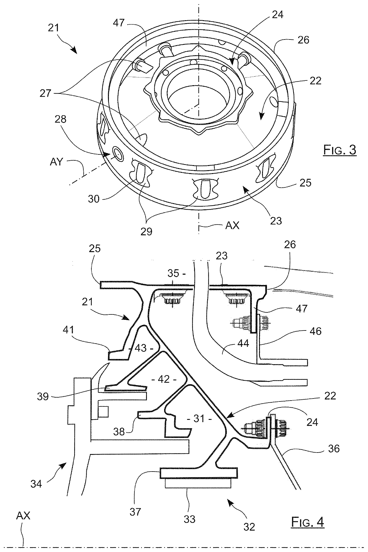
[0037]According to the invention, the bearing support is a metal component formed from a single piece by additive manufacturing, including in particular a fastening cone and a cylindrical element surrounding this cone, instead of manufacturing them separately to then assemble them.

[0038]This bearing support that appears in FIG. 3 where it is marked by 21 includes a cone frustum or cone 22, that has its large-diameter periphery extended by a generally cylindrical element 23, and having its small-diameter periphery extended by a ring 24. The bearing support 21 has a general shape of revolution about an axis AX coincident with the longitudinal axis of the engine wherein it is intended to be mounted, the cone 22 and the cylindrical element 23 having this axis AX as axis of revolution.

[0039]The cylindrical element 23 extends from a first edge 25 to a circular second edge 26 that substantially has the same diameters while still being spaced from one another along the ...


PUM

PropertyMeasurementUnit
angleaaaaaaaaaa
clearance angleaaaaaaaaaa

Abstract

A method for producing, by additive manufacturing, a part including at least one surface that must be held during the manufacturing, the method including: a step of forming a raw part by additive manufacturing, the raw part including a support including a pillar and a head which is an alveolar element connecting the pillar to the surface to be held; and a step of detaching the support from the rest of the raw part.

Description

TECHNICAL FIELD[0001]The present invention relates to the forming of a bearing support of an aircraft engine by additive manufacturing.GENERAL CONTEXT OF THE INVENTION[0002]A bypass turbine engine includes an inlet sleeve receiving the air upstream that is aspirated by a low-pressure compressor, before being divided into a central primary flow and a secondary flow surrounding the primary flow. After having passed the low-pressure compressor, the secondary flow is propelled downstream to generate a thrust by being blown around the primary flow, upstream and downstream being defined with respect to the direction of flow of fluid in the turbine engine.[0003]After having passed the low-pressure compressor, the primary flow passes through a high-pressure compressor before reaching a combustion chamber. This primary flow is then expanded in a high-pressure turbine engine linked in rotation with the high-pressure compressor, then in a low-pressure turbine linked in rotation to the low-pres...

Claims


Application Information

Patent Timeline
Patent Type & Authority Applications(United States)
IPC IPC(8): B22F3/105B33Y10/00B33Y80/00B33Y40/00B22F5/00F01D25/16
CPCB22F3/1055B33Y10/00B33Y80/00F05D2240/50B22F5/009F01D25/162B22F2003/1058B33Y40/00B22F3/24B22F2003/247B29C64/40Y02P10/25B22F10/66B22F10/47B22F10/28B22F10/00
Inventor OVAERE, NICOLASBUNEL, JACQUES MARCEL ARTHURGRICOURT, THOMASSOMAZZI, PAUL ANDRÉZAMBELLI, SYLVAIN
Owner SN DETUDE & DE CONSTR DE MOTEURS DAVIATION S N E C M A
Why Eureka
Try Eureka