
Cable connector

a cable connector and connector technology, applied in the direction of electrical cable installation, coupling device connection, coupling base/case, etc., can solve the problems of affecting the electrical connection between the cable connector and the bushing, the inability to resist radial deformation, looseness and clearance, etc., to improve the electrical connection, the effect of reducing the number of screws

Active Publication Date: 2021-01-14
CHARDON TAIWAN CORP
View PDF0 Cites 1 Cited by
  • Summary
  • Abstract
  • Description
  • Claims
  • Application Information

AI Technical Summary

Benefits of technology

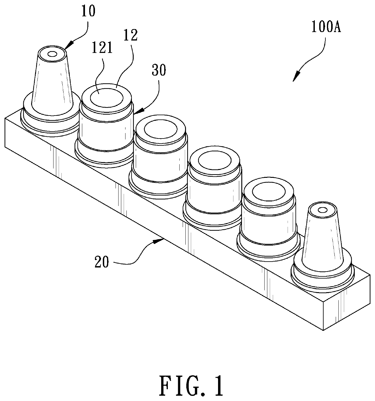
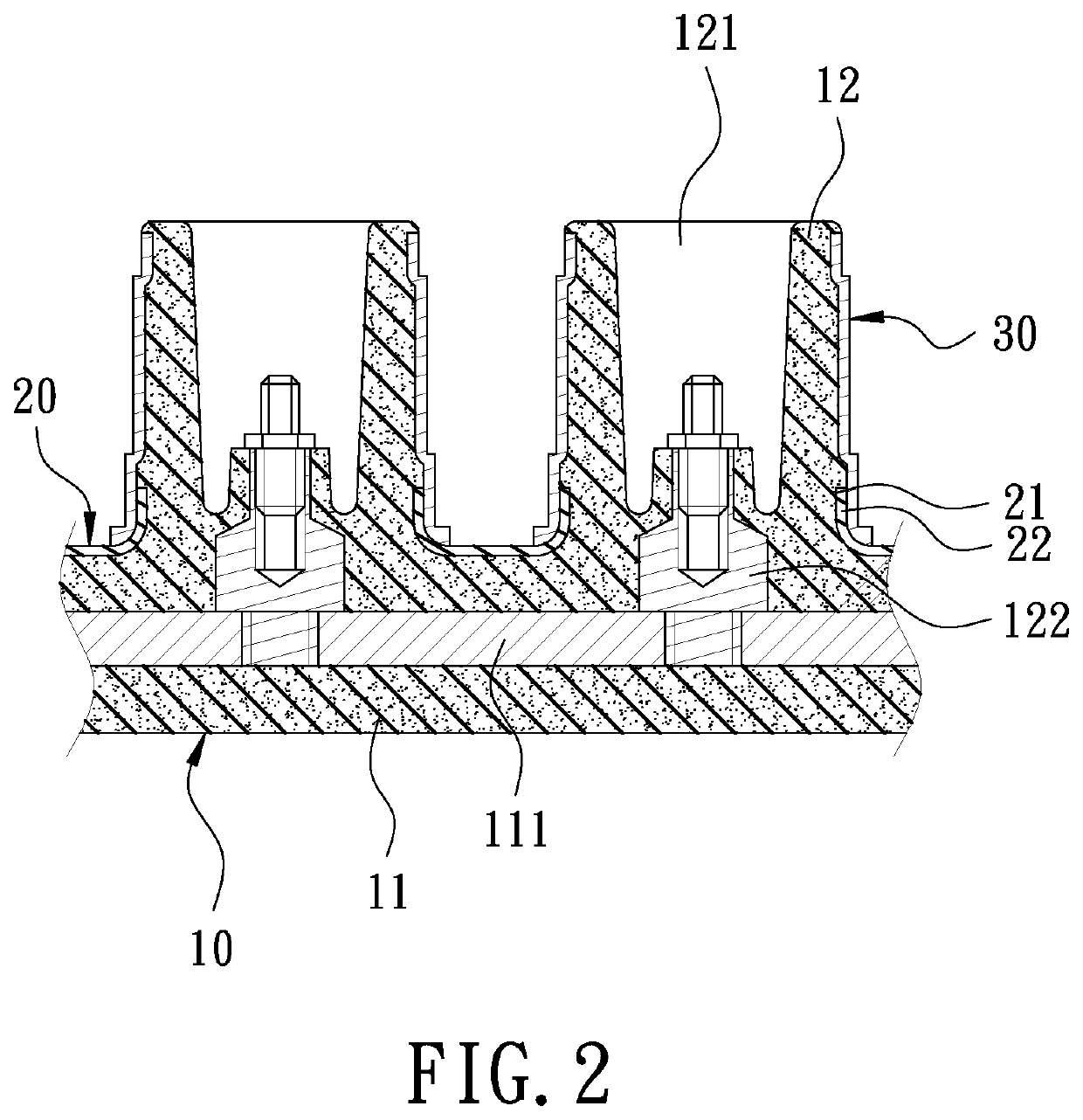
The present invention provides a cable connector that can resist deformation and improve the electrical connection. The connector has a hard casing made of a rigid material on the outer wall surface of the connecting portion. This hard casing prevents the connecting portion from deforming when a bushing of a cable is inserted, resulting in a better electrical connection.

Problems solved by technology

However, the cable connector is usually made of a soft material, such as rubber, and cannot resist radial deformation.
When the user inserts the bushing of the cable into the groove of the socket, the socket will be deformed by insertion of the bushing, so that the bushing cannot be tightly and securely connected to the socket and it is easy to cause looseness and clearance when pulled by external force, which affects the electrical connection between the cable connector and the bushing.

Method used


Image

  • Cable connector
  • Cable connector
  • Cable connector

Examples


first embodiment

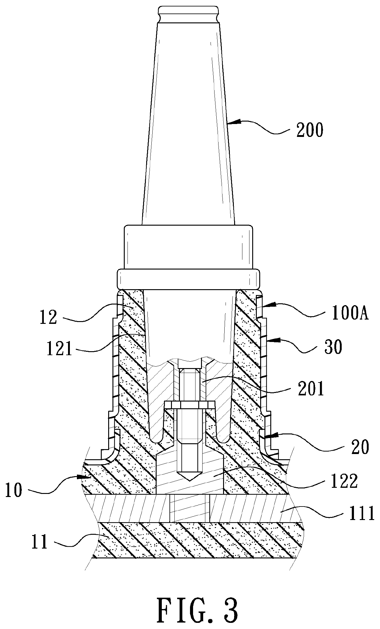
[0018]FIG. 3 is a schematic view in accordance with the present invention when in use. The cable connector 100A is in cooperation with a bushing 200 of a cable when in use. The bushing 200 is inserted into the connecting portion 12 through the connecting groove 121, and a connecting terminal 201 of the busing 200 is threadedly connected to the connecting terminal 122 of the connecting portion 12. Because the hard casing 30 is provided on the outer wall surface of the connecting portion 12, and the hard casing 30 is made of a plastic material having higher rigidity than the soft body 10, when the bushing 200 is inserted in the connecting groove 121, the hard casing 30 is configured to resist radial deformation, so that the connecting portion 12 will not be deformed by insertion of the bushing 200. Therefore, the connection between the connecting portion 12 and the bushing 200 is tighter and firmer to ensure that no looseness or clearance occurs when pulled by an external force, there...

fourth embodiment

[0021]FIG. 6 is a partial cross-sectional view in accordance with the present invention. This embodiment discloses a cable connector 100C in the form of an elbow. The cable connector 100C has the soft body 10. The soft body 10 is in an L-shape. One end of the soft body 10 is provided with the connecting portion 12. The connecting portion 12 is concavely formed with the connecting groove 121. The bottom of the connecting groove 121 is provided with the connecting terminal 122. The outer wall surface of the connecting portion 12 is provided with the hard casing 30. Thereby, the hard casing 30 also provides an anti-deformation effect to improve the electrical connection.


PUM

PropertyMeasurementUnit
rigidityaaaaaaaaaa
adhesiveaaaaaaaaaa
softaaaaaaaaaa

Abstract

A cable connector includes a soft body. The soft body has at least one connecting portion. An outer wall surface of the connecting portion is provided with a hard casing. The soft body is made of a soft material, such as rubber and silicone rubber. The hard casing is made of a hard material, such as plastic, and has higher rigidity than the soft body. When a bushing of a cable is inserted into the connecting groove of the connecting portion, the hard casing is configured to resist deformation, so that the connecting portion will not be deformed by insertion of the bushing, thereby improving the electrical connection between the cable connector and the bushing.

Description

FIELD OF THE INVENTION[0001]The present invention relates to a cable connector, and more particularly to a cable connector applied to high-voltage electrical equipment.BACKGROUND OF THE INVENTION[0002]Generally, high-voltage electrical equipment often uses a cable connector to connect with external cables. Taking a common cable connector in the form of a reducing tap well as an example, the cable connector usually has at least one socket. The socket has a groove. A conductive screw is provided at the bottom of the groove. The cable is provided with a corresponding bushing. The bushing is provided with a conductive screw hole corresponding to the conductive screw. Thereby, the bushing is inserted into the groove, and the conductive screw is screwed with the conductive screw hole to connect the cable to the cable connector.[0003]However, the cable connector is usually made of a soft material, such as rubber, and cannot resist radial deformation. When the user inserts the bushing of th...

Claims


Application Information

Patent Timeline
Patent Type & Authority Applications(United States)
IPC IPC(8): H01R13/53H01R13/504H01R13/502
CPCH01R13/53H01R13/5025H01R13/504H02G15/064
Inventor LIANG, TSUNG-MIEN
Owner CHARDON TAIWAN CORP
Learn More