Eureka AIR delivers breakthrough ideas for toughest innovation challenges, trusted by R&D personnel around the world.

Radio frequency circuit and communication device

a radio frequency circuit and communication device technology, applied in the direction of transmission, electrical equipment, etc., can solve the problems of intermodulation distortion, deterioration of isolation between signals, etc., and achieve the effect of reducing intermodulation distortion

Active Publication Date: 2021-01-14
MURATA MFG CO LTD
View PDF0 Cites 1 Cited by
  • Summary
  • Abstract
  • Description
  • Claims
  • Application Information

AI Technical Summary

Benefits of technology

The patent text is about a way to reduce intermodulation distortion when multiple communication systems use radio frequency signals at the same time. The invention is a radio frequency circuit and communication device that can help reduce this issue.

Problems solved by technology

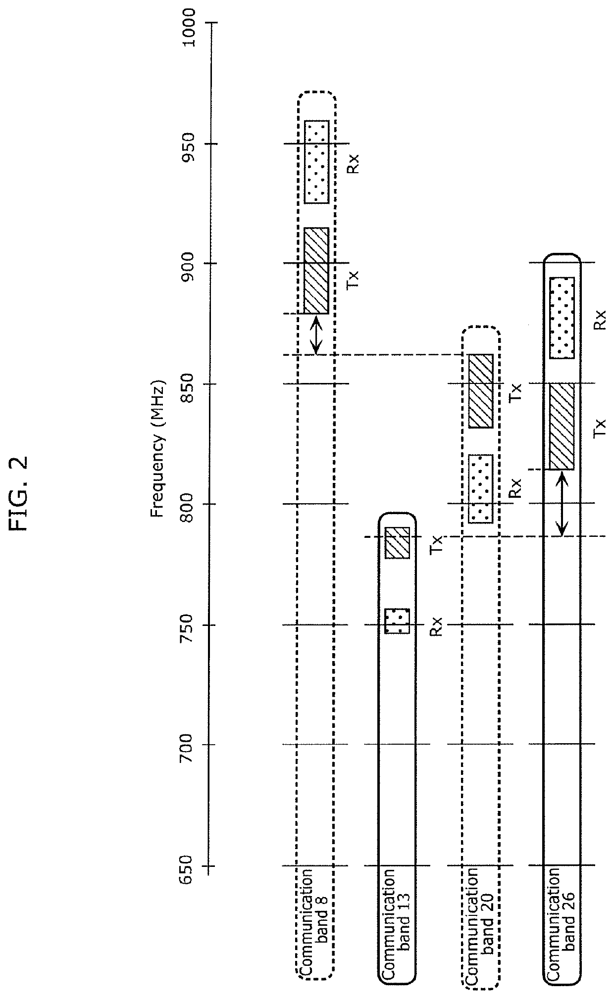
However, when a single transfer circuit simultaneously transmits radio frequency signals having frequency ranges in such two communication bands whose transmission bands are adjacent to each other, isolation between the signals deteriorates, which leads to a problem that intermodulation distortion occurs.

Method used


Image

  • Radio frequency circuit and communication device
  • Radio frequency circuit and communication device
  • Radio frequency circuit and communication device

Examples


Embodiment Construction

[0020]The following describes in detail embodiments of the present disclosure, with reference to examples and drawings. Note that the embodiments described below each show a general or specific example. The numerical values, shapes, materials, elements, and the arrangement and connection of the elements, for instance, described in the following embodiment are examples, and thus are not intended to limit the present disclosure. Among the elements in the following embodiment, elements not recited in any of the independent claims are described as arbitrary elements. Furthermore, the sizes and the ratios of the sizes of elements illustrated in the drawings are not necessarily accurate.

1 Configuration of Radio Frequency Circuit 1 and Communication Device 6

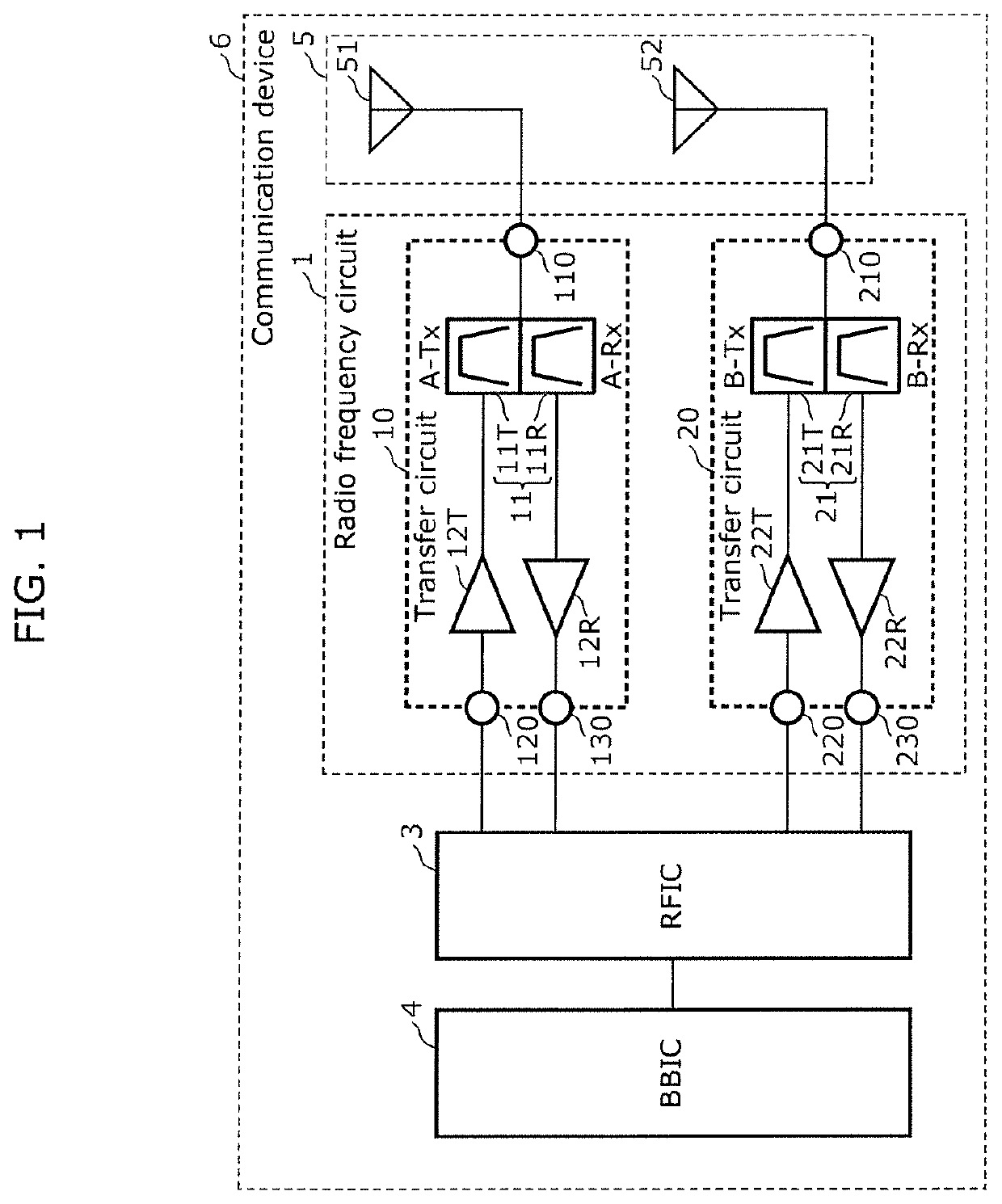
[0021]FIG. 1 illustrates a circuit configuration of radio frequency circuit 1 and communication device 6 according to an embodiment. As illustrated in FIG. 1, communication device 6 includes radio frequency circuit 1, antenna circuit 5,...


PUM


Abstract

A radio frequency circuit can transfer radio frequency signals used in first and second communication systems, and includes: a first transfer circuit that transfers a radio frequency signal having a frequency range in a first communication band having first transmission and receiving bands; and a second transfer circuit that transfers a radio frequency signal having a frequency range in a second communication band having second transmission and receiving bands. The radio frequency circuit can simultaneously transmit transmission signals having frequency ranges in the first and second communication bands using the first and second transfer circuits. The first receiving band is lower than the first transmission band, the first transmission band is lower than the second transmission band, and the second transmission band is lower than the second receiving band. The first and second transfer circuits are mounted on different mounting boards.

Description

CROSS REFERENCE TO RELATED APPLICATION[0001]The present application is based on and claims priority of Japanese Patent Application No. 2019-129004 filed on Jul. 11, 2019. The entire disclosure of the above-identified application, including the specification, drawings and claims is incorporated herein by reference in its entirety.BACKGROUND[0002]The present disclosure relates to a radio frequency circuit and a communication device that includes the radio frequency circuit.[0003]There has been a demand that a radio frequency front-end circuit support multiband and multi-mode technology to simultaneously transfer a plurality of radio frequency signals with low loss.[0004]U.S. Unexamined Patent Application Publication No. 2016 / 0127015 discloses a receiving module (a transfer circuit) having a configuration in which a plurality of filters having different passbands are connected to an antenna via a multiplexer.BRIEF SUMMARY[0005]The receiving module (the transfer circuit) described in U....

Claims


Application Information

Patent Timeline
Patent Type & Authority Applications(United States)
IPC IPC(8): H04B1/00H04B1/40
CPCH04B1/0067H04B1/40H04B1/006
Inventor ONO, ATSUSHITANAKA, SATOSHIMORI, HIROTSUGU
Owner MURATA MFG CO LTD
Why Eureka
Eureka Blog
Learn More