
Motorized walking shoes

a technology for walking shoes and shoes, applied in the direction of skates, sports equipment, etc., can solve the problem that the user of power-assisted footwear has limited control over the speed of the footwear, and achieve the effect of preventing substantial twisting

Pending Publication Date: 2021-01-21
TULI RAJA SINGH
View PDF0 Cites 7 Cited by
  • Summary
  • Abstract
  • Description
  • Claims
  • Application Information

AI Technical Summary

Benefits of technology

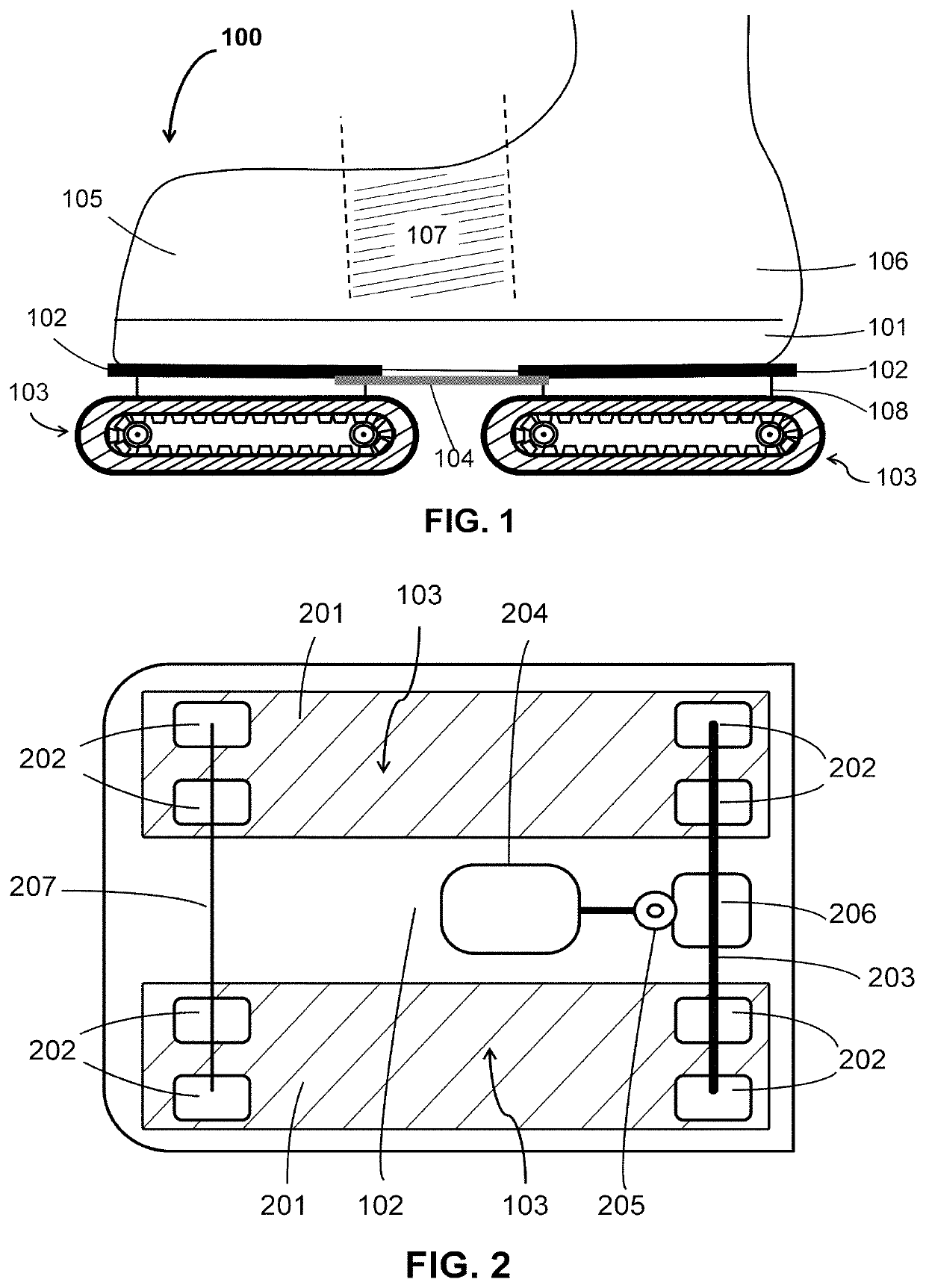
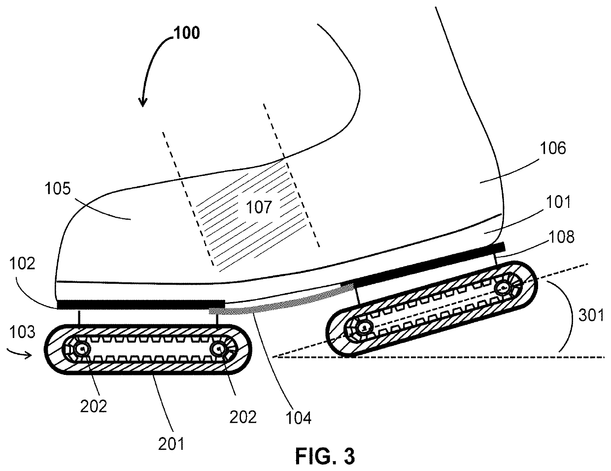
The present invention is addressed to information regarding the mechanisms of conveyor assemblies designed to handle external forces generated by impact. The conveyor assemblies are designed to operate continuously, without being disrupted despite intermittent external forces. Additionally, the invention includes a single plate connected to the shoe sole, which is aligned longitudinally from the toe area to the heel area and is connected to conveyor assemblies. The single plate is made of a material that is twistable or bendable to a small extent, but remains stiff enough to prevent damage to the shoe. The technical effect of this invention is the improved design of conveyor assemblies and the single plate connection to the shoe to enhance resistance to external forces and promote smooth operation.

Problems solved by technology

Moreover, in most of the prior art cases, the user of the power-assisted footwear has limited control over the speed of the footwear.

Method used


Image

  • Motorized walking shoes
  • Motorized walking shoes
  • Motorized walking shoes

Examples


first embodiment

[0085]In a first embodiment depicted in the third graph 1303 of FIG. 13A, the speed of the supplementary motion provided by the motorized walking shoes 100, Sc,t, is steady within each step and is equal to the difference between the user's intended walking speed, Si,t, at the beginning of a given step and the speed that is strictly contributed by the user's walking motion, Su,t, at the beginning of that same given step. Here as well, the speed of the first shoe 100 is shown with a continuous line 1309, while the speed of the second shoe 100 is shown with a dashed line 1310, and the shoe 100 that has a positive Sc,t is always the one that is lying on the underlying surface. In the present embodiment, the speed of the supplementary motion provided by the motorized walking shoes 100 is determined at discrete intervals, at the beginning of each time unit. Although this embodiment involves relatively abrupt transitions that may destabilize some users, it features the benefit of more imme...

second embodiment

[0086]In a second embodiment depicted in the fourth graph 1304 of FIG. 13A, the speed of the supplementary motion provided by the motorized walking shoes 100, Sc,t, is gradually adjusted on a continuous basis and is equal to the difference between the user's intended walking speed, Si,t-1, at the previous time unit and the speed that is strictly contributed by the user's walking motion, Su,t-1, at the previous time unit. As previously mentioned, in the present embodiment, Sc,t=Si, t-1−Su,t-1=(X−1) Su,t-1. Here as well, the speed of the first shoe 100 is shown with a continuous line 1311, while the speed of the second shoe 100 is shown with a dashed line 1312, and the shoe 100 that has a positive Sc,t is always the one that is lying on the underlying surface. Although this embodiment involves a greater lag before the user's actual walking speed equals the user's intended walking speed, Si,t, it features smoother speed transitions.

third embodiment

[0087]In a third embodiment depicted in the first graph 1351 of FIG. 13B, Su,t for a given time unit is assessed or calculated with reference to the peak speeds 1307, and the speed of the supplementary motion provided by the motorized walking shoes 100, Sc,t, is immediately adjusted at each mid-step for the shoe 100 that is lying on the underlying surface. In the present embodiment, immediately upon assessment at a mid-step of a new intended speed by the user, the speed of the supplementary motion provided by the motorized walking shoes 100, Sc,t, becomes equal to the difference between the user's newly-assessed intended walking speed, Si,t, at the mid-step and the overall speed that is strictly contributed by the user's walking motion, Su,t, at the mid-step. Here as well, the speed of the first shoe 100 is shown with a continuous line 1355, while the speed of the second shoe 100 is shown with a dashed line 1356, and the shoe 100 that has a positive Sc,t is always the one that is ly...


PUM


Abstract

A motorized personal transportation article is described which transports a person by wearing a pair of power-assisted motorized shoes, wherein the shoes provide an increase in a user's walking speed in a forward walking action through supplementary motion of moving or propelling means based on an intended walking speed of the user, such that when a user's intended walking speed changes or when a user intends to substantially decelerate or immobilize, the speed of the supplementary motion can be adjusted before the step is completed. The sole of each of the shoes houses at least one plate coupled to moving or propelling means such as conveyor assemblies, and the moving or propelling means are designed to neutralize forces acting to disrupt the operation of the moving or propelling means during a forward walking action or the balance and comfort of the user.

Description

CROSS-REFERENCE TO RELATED APPLICATIONS[0001]This application is a continuation-in-part of application Ser. No. 15 / 353,813 filed on Nov. 17, 2016.BACKGROUND OF THE INVENTIONField of the Invention[0002]The present invention relates to motorized personal transport means, more specifically, the field of power-assisted footwear to transport a user. The present invention also relates to active means of transport, which are operated through user actions.Description of the Related Art[0003]Power-assisted footwear enabling travel or motion of a user is known as a means of personal transportation, although it has generally been limited to the concept of powered or motorized skates, where roller skates or in-line skates, thereby involving a skating motion. Prior art examples of these endeavors include U.S. Pat. Nos. 3,876,032, 4,508,187, 5,236,058, 5,797,466 and 6,059,062. In these cases, when the power-assisted footwear is worn by a user, the natural walking movement of the user contributes ...

Claims


Application Information

Patent Timeline
IPC IPC(8): A43B3/00A43B13/14A63C17/10A63C17/12
CPCA43B3/0005A63C17/12A63C17/10A43B13/141A43B3/0036A43B13/16A43B13/28A43C19/00A63C17/26A63C2203/10A63C2203/42A43B13/143A43B3/34
Inventor TULI, RAJA SINGH
Owner TULI RAJA SINGH
Learn More