Expanding intervertebral implants

a technology of intervertebral implants and spacers, which is applied in the field of stabilizing adjacent vertebrae of the spine, can solve the problems of reducing disc height and possible annulus fibrosis delamination, and affecting the function of discs, etc., and achieves the effect of increasing the height of the spacer

Active Publication Date: 2021-01-21
GLOBUS MEDICAL INC
View PDF0 Cites 8 Cited by
  • Summary
  • Abstract
  • Description
  • Claims
  • Application Information

AI Technical Summary

Benefits of technology

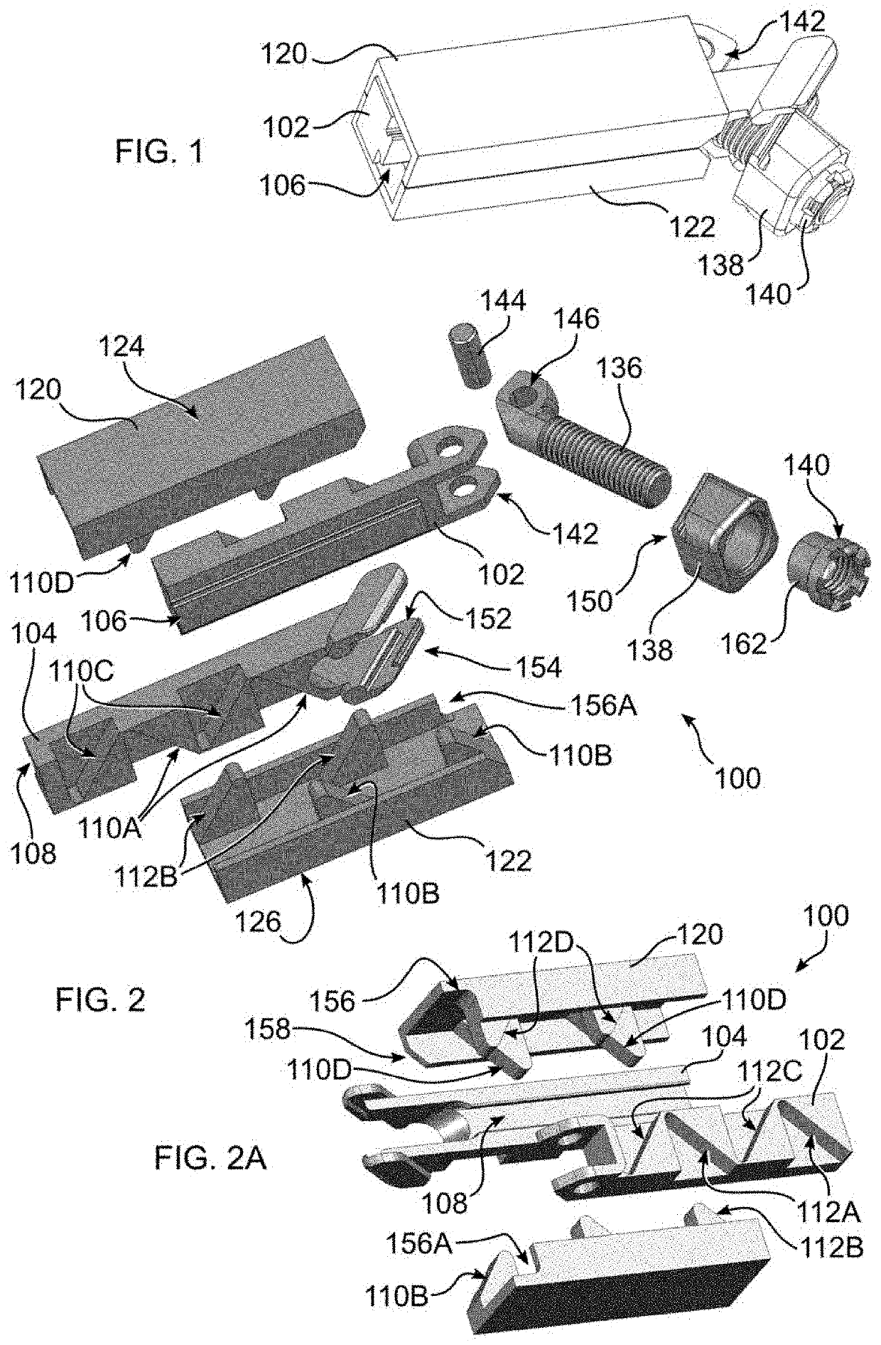
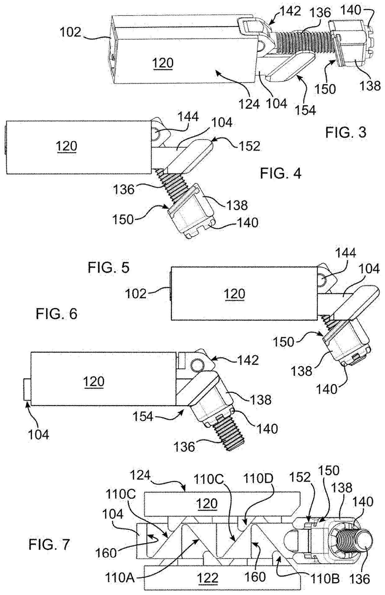
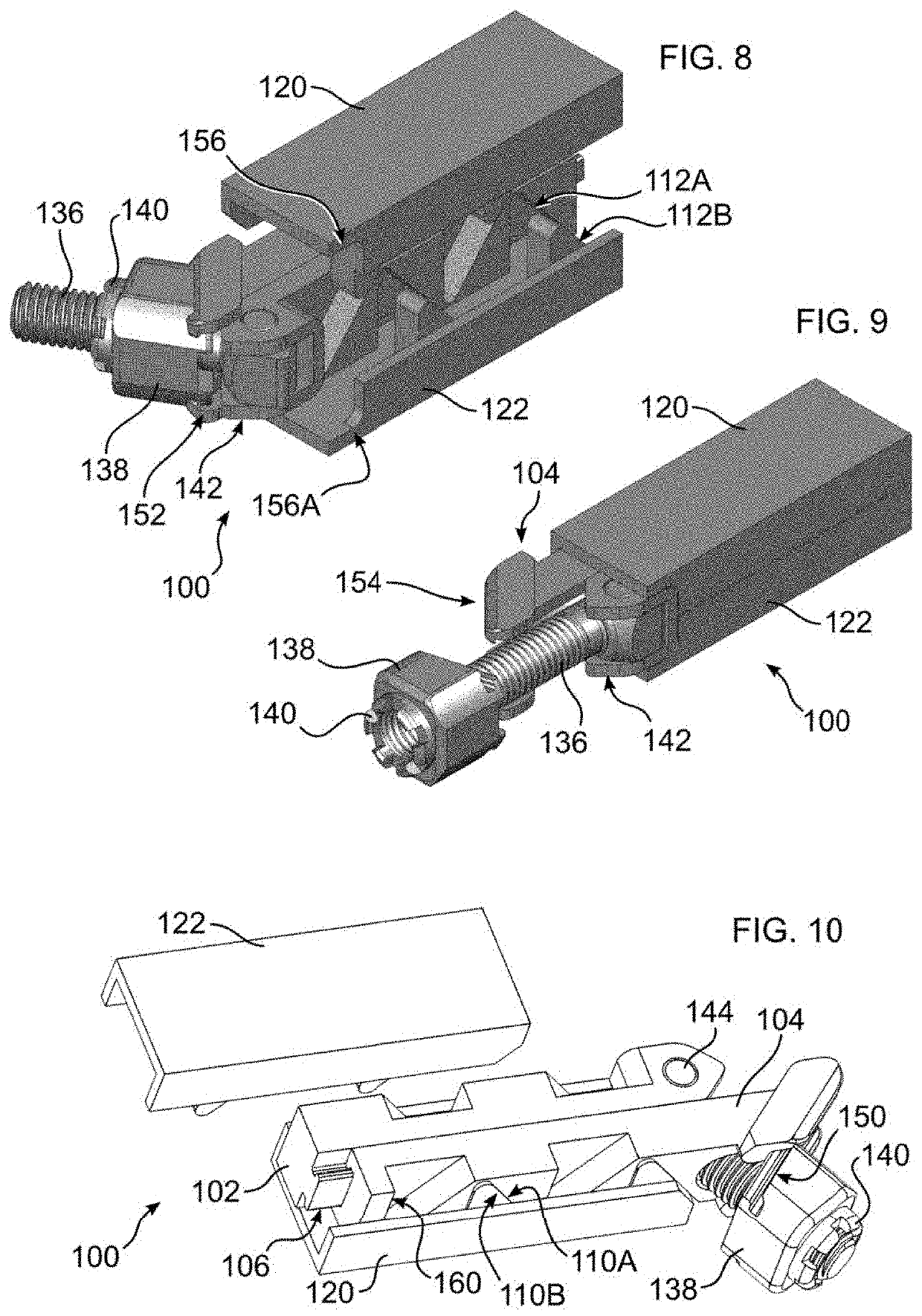
[0007]In an embodiment of the disclosure, a spacer for separating bones of a joint comprises first and second endplates, each having a bone engaging surface, at least two cams each having an inclined cam surface, the cams positioned on a side opposite to the bone engaging surface; first and second slides, each having at least two ramps each having an inclined surface and each engaged with an inclined cam surface of a cam of an endplate, the first slide having an angled portion at a proximal end, the second slide having a first hinge portion; a threaded shaft having a second hinge portion cooperative with the first hinge portion to connect the shaft to the second slide and to enable the shaft to form a changeable angle with respect to the second slide; a nut threadably engaged with the shaft, the nut forming an interference with the angled portion of the first slide when the nut is threadably advanced upon the shaft, thereby driving the first slide with respect to the second slide causing relative moving engagement of the at least two cams and the at least two ramps to drive the endplates relatively apart and to thereby increase a height of the spacer.

Problems solved by technology

Many factors can adversely alter the composition and structure of the intevertebral disc, such as normal physiological aging, mechanical injury / trauma, and / or disease, resulting in impairment or loss of disc function.
Therefore, in normal aging the disc progressively dehydrates, resulting in a decrease in disc height and possible de-lamination of the annulus fibrosus.
Bones of the spine, and bony structures, generally, are susceptible to a variety of weaknesses that can affect their ability to provide support and structure.

Method used


Image

  • Expanding intervertebral implants
  • Expanding intervertebral implants
  • Expanding intervertebral implants

Examples


Embodiment Construction

[0033]As required, detailed embodiments are disclosed herein; however, it is to be understood that the disclosed embodiments are merely examples and that the systems and methods described below can be embodied in various forms. Therefore, specific structural and functional details disclosed herein are not to be interpreted as limiting, but merely as a basis for the claims and as a representative basis for teaching one skilled in the art to variously employ the present subject matter in virtually any appropriately detailed structure and function. Further, the terms and phrases used herein are not intended to be limiting, but rather, to provide an understandable description of the concepts.

[0034]The terms “a” or “an”, as used herein, are defined as one or more than one. The term plurality, as used herein, is defined as two or more than two. The term another, as used herein, is defined as at least a second or more. The terms “including” and “having,” as used herein, are defined as comp...


PUM


Abstract

A joint spacer has first and second endplates, with each having a bone engaging surface, and at least two cams with an inclined cam surface positioned on an opposite side. First and second slides, each having ramps with an inclined surface are engaged with the cams of the endplate. The first slide has an angled portion at an end, and the second slide has a hinge portion. A threaded shaft has a hinge portion connected to the slide hinge portion, connecting the shaft to the slide, enabling the shaft to pivot. A nut is threaded to the shaft, and can contact and interfere with the angled portion of the first slide to drive the first slide with respect to the second slide. This results in engagement of the cams and ramps to drive the endplates apart to increase the spacer height.

Description

FIELD OF THE INVENTION[0001]This invention relates to stabilizing adjacent vertebrae of the spine by inserting an intervertebral spacer, and more particularly an intervertebral spacer that is adjustable in height.BACKGROUND OF THE INVENTION[0002]The vertebral or spinal column (spine, backbone) is a flexible assembly of vertebrae stacked on top of each other extending from the skull to the pelvic bone which acts to support the axial skeleton and to protect the spinal cord and nerves. The vertebrae are anatomically organized into four generalized body regions identified as cervical, thoracic, lumbar, and sacral; the cervical region including the top of the spine beginning in the skull, the thoracic region spanning the torso, the lumbar region spanning the lower back, and the sacral region including the base of the spine ending with connection to the pelvic bone. With the exception of the first two cervical vertebrae, cushion-like discs separate adjacent vertebrae, i.e. intervertebral ...

Claims


Application Information

Patent Timeline
Patent Type & Authority Applications(United States)
IPC IPC(8): A61F2/44
CPCA61F2/4425A61F2002/30538A61F2002/443A61F2/4455A61F2/447A61F2/4611A61F2002/30261A61F2002/30266A61F2002/30331A61F2002/3037A61F2002/30383A61F2002/30398A61F2002/30405A61F2002/30471A61F2002/30476A61F2002/30482A61F2002/30507A61F2002/30528A61F2002/30537A61F2002/3054A61F2002/30556A61F2002/30579A61F2002/30624A61F2002/4628A61F2002/30153A61F2002/30329
Inventor WEIMAN, MARKGLERUM, CHADHESSLER, TYHILL, ALBERT
Owner GLOBUS MEDICAL INC
Why Eureka
Try Eureka