Method for integrating prediction result

Inactive Publication Date: 2021-01-21
HITACHI LTD
View PDF0 Cites 0 Cited by
  • Summary
  • Abstract
  • Description
  • Claims
  • Application Information

AI Technical Summary

Benefits of technology

The patent text describes a system that uses machine learning to predict failures in a factory. Even if the system doesn't predict the failure, a human user may notice specific symptoms. The system can then analyze data from other similar factories and determine the cause of the failure. This helps identify the cause more quickly and helps maintain the production line and increase production rates. The system can also reduce the time required to determine the cause of failures that have not happened frequently in the factory before.

Problems solved by technology

Failures can include the equipment fault occurring in the factories or phenomena indicative of impending failure for the factories, for example, which factory equipment will be broken next or decreasing yield rate.
However, if there are certain types of failures that have not occurred in the past or occur very rarely (e.g., once a year), machine learning models may be unable to predict such failures.
Further, some data relevant to the failure are not always collected because the users may not know the relevance.
Under these circumstances, in some case, it can be difficult for users to find the cause of failure even after something had happened.
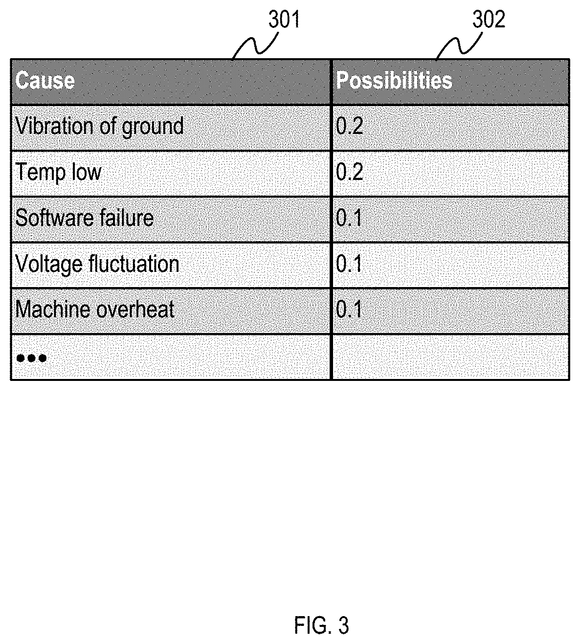
For example, if the yield rate decreases in a semiconductor factory in a manner that has not occurred before, and the root cause is the vibration of the ground by made by a train, it can be hard to determine the cause if the user had no idea that the yield rate is relevant to the vibration of the ground.
In this case, it can take a long time to determine the cause and take counter measures.
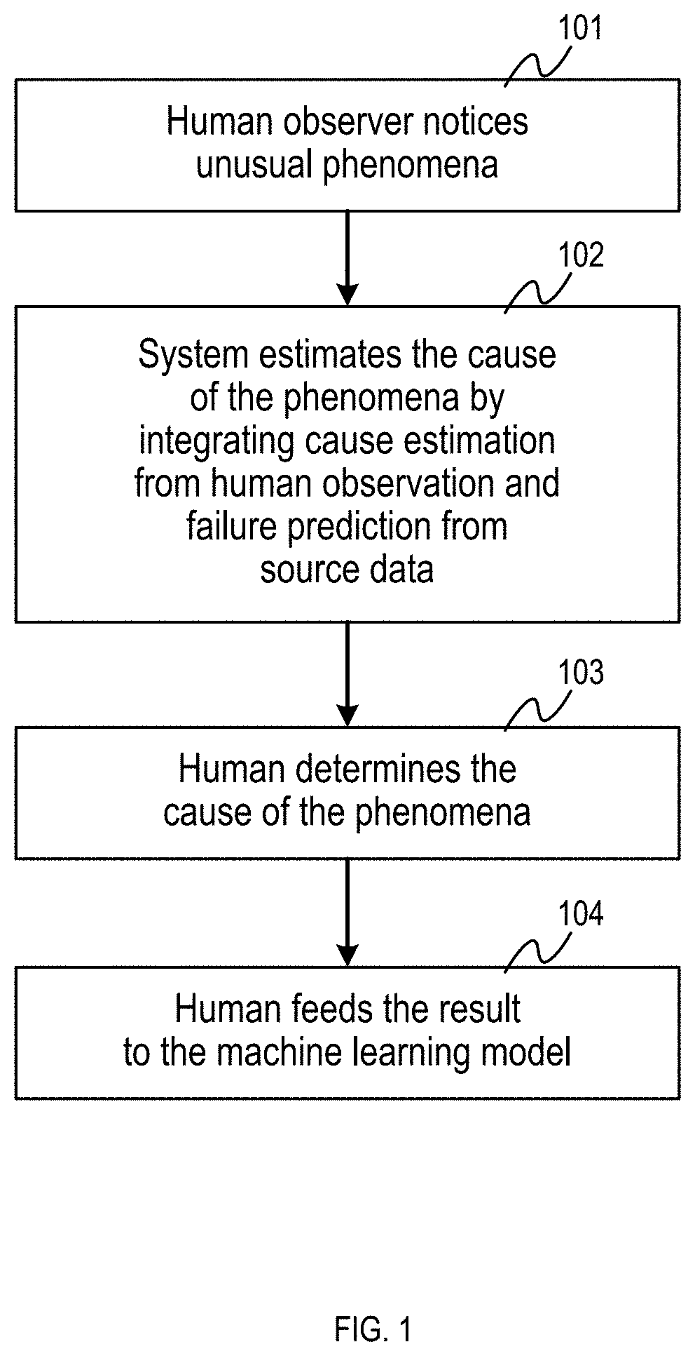
In example implementations, even if the failure prediction model cannot predict the failure, a human user may notice specific phenomena when the failure occurred.

Method used


Image

  • Method for integrating prediction result
  • Method for integrating prediction result
  • Method for integrating prediction result

Examples


Embodiment Construction

[0028]The following detailed description provides further details of the figures and example implementations of the present application. Reference numerals and descriptions of redundant elements between figures are omitted for clarity. Terms used throughout the description are provided as examples and are not intended to be limiting. For example, the use of the term “automatic” may involve fully automatic or semi-automatic implementations involving user or administrator control over certain aspects of the implementation, depending on the desired implementation of one of ordinary skill in the art practicing implementations of the present application. Selection can be conducted by a user through a user interface or other input means, or can be implemented through a desired algorithm. Example implementations as described herein can be utilized either singularly or in combination and the functionality of the example implementations can be implemented through any means according to the d...


PUM


Abstract

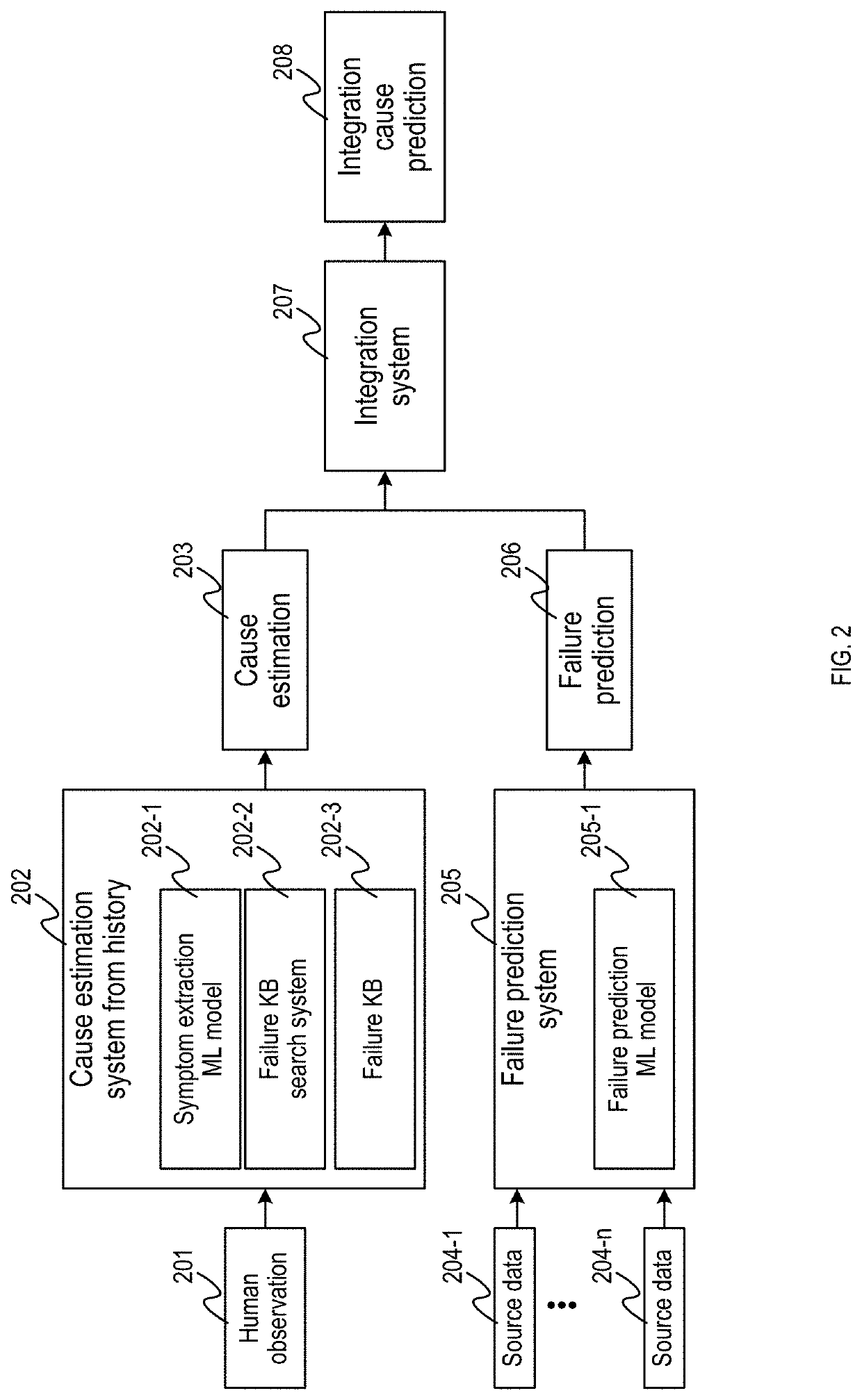
Example implementations described herein involve integrating human observations into results of a machine learning process to generate an integrated failure prediction and updated machine learning models from human observations. Example implementations can involve systems and methods that, for receipt of a user input indicative of a failure symptom at a facility, conducting cause estimation on the failure symptom to determine a first set of probabilities associated with a first set of causes of the failure symptom; and integrating the first set of probabilities and first set of causes into a process configured to provide a second set of probabilities and a second set of causes of the failure symptom based on a set of potential failures associated with a third set of probabilities provided from a machine learning process configured to output the set of potential failures and the third set of probabilities based on sensor data from the facility.

Description

BACKGROUNDField[0001]The present disclosure is generally related to fault prediction, and more specifically, to systems and methods that conduct fault prediction from an integration of machine learning systems and human controlled systems.Related Art[0002]As machine learning implementations improve, fault prediction models can be developed more easily. To use such implementations, companies who own factories can develop the model to predict failures from sensor data, images, videos, and / or repair history. Failures can include the equipment fault occurring in the factories or phenomena indicative of impending failure for the factories, for example, which factory equipment will be broken next or decreasing yield rate. Such models can instruct the managers of factories to know of failures. The managers can take measurements or conduct preventative maintenance based on the predicted failures, and can thereby maintain the production line of the factory to continuously operate and reduce ...

Claims


Application Information

Patent Timeline
IPC IPC(8): G06N20/00G06N5/04
CPCG06N20/00G06N5/048G06N5/045G05B23/024G05B23/0283G06N3/044
Inventor SUGIMOTO, KENYOSHIDA, MICHIKO
Owner HITACHI LTD
Why Eureka
Try Eureka