
Integrated electrospray ion source

a technology of ion source and ion source, which is applied in the field of ion source, can solve the problems of difficult to obtain optimal performance with a conventional ion source, time-consuming and laborious, and achieve the effect of reducing the tediousness associated with ion source optimization and saving tim

Active Publication Date: 2021-01-21
DH TECH DEVMENT PTE
View PDF11 Cites 0 Cited by
  • Summary
  • Abstract
  • Description
  • Claims
  • Application Information

AI Technical Summary

Benefits of technology

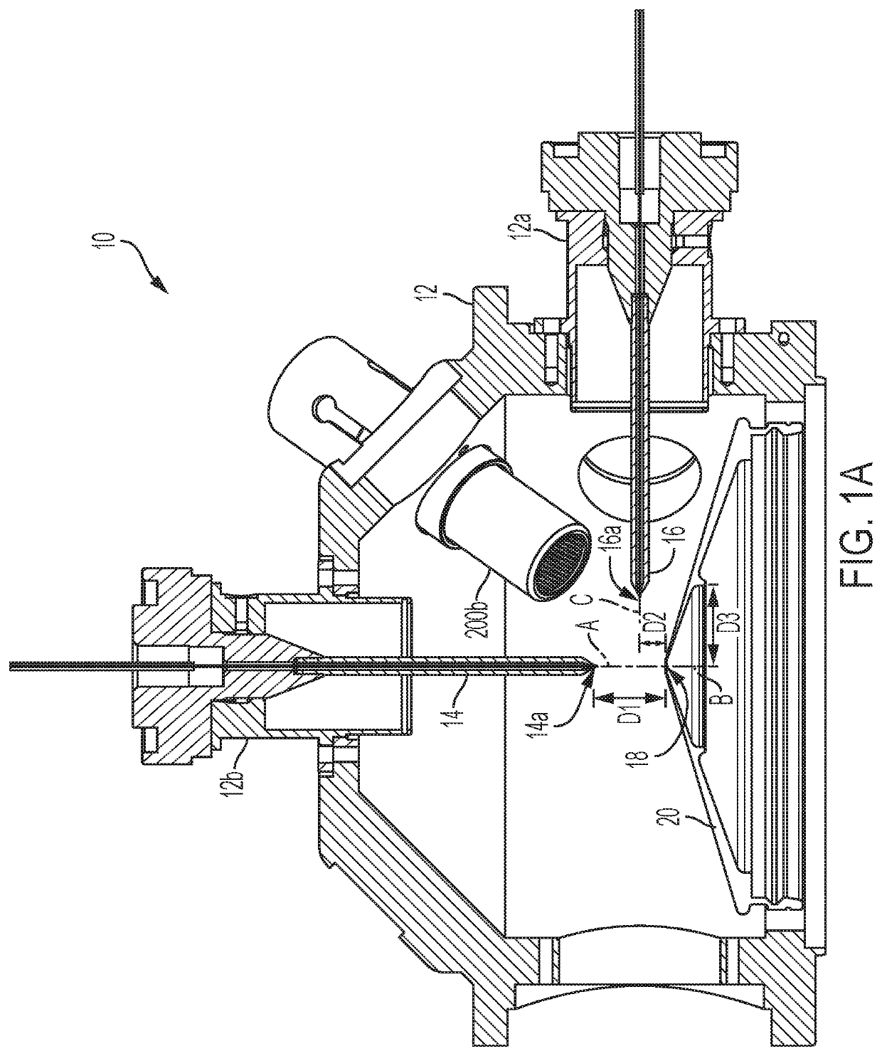
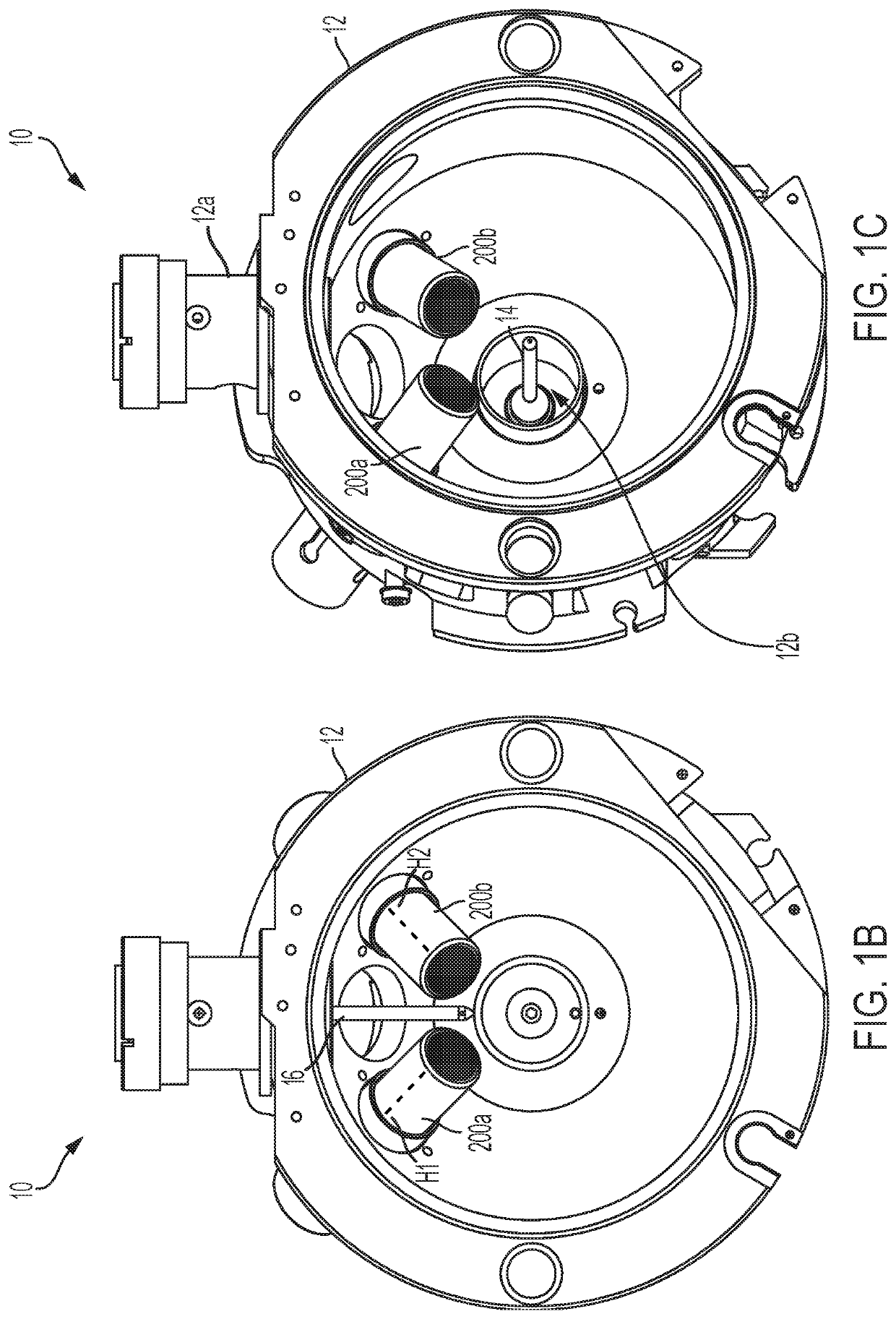
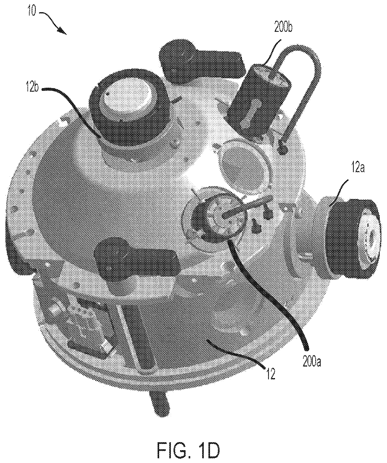
The patent describes an ion source for mass spectrometry that includes two ion probes with fixed emitter positions. The probes can be independently coupled to the housing, allowing for operation with either or both probes. The ion source can also include heaters to assist in desolvation of charged microdroplets generated by the probes. The mass spectrometer to which the ion source is coupled can include circuitry to recognize which probe is coupled. The system can also include an exhaust port and additional gas flows to control source pressure. The technical effects of this patent include reducing the tediousness associated with ion source optimization, saving time, and improving the accuracy of mass spectrometry analysis.

Problems solved by technology

Additionally, the protrusion of the emitter from the discharge end of the probe often requires adjustment, which in turn requires re-optimization of nebulization gas and ESI electrical potential.
Sensitivity performance optimization can be further complicated when the user attempts to determine optimal operational parameters for a mixture of compounds.
In general, it is not possible to determine a single set of operational parameters which would produce optimal sensitivity for all compounds in a mixture, and the “optimal” parameters usually involve a performance compromise for a subset of the compounds in the mixture.
As such, obtaining optimal performance with a conventional ion source is time consuming and can be difficult, even for experienced users.
Such replacement of probes can be, however, cumbersome and time consuming.
Specifically, in many embodiments, the emitter of each probe extends out of the probe body at the discharge end by a fixed amount, which is not adjustable by a user.
In other words, the emitter of each probe has a portion that extends beyond the discharge end of the probe and the length of this external portion of the emitter is non-adjustable by a user.
Further, in some embodiments, the first and the second probes can be positioned in the housing such that the discharge tips thereof are non-adjustably disposed relative to the orifice of the curtain plate.
In other words, in such embodiments, the orientation and the distance of the discharge tips of the probes relative to the orifice of the curtain plate are fixed and cannot be adjusted by a user.
Further, a cap utilized to plug a non-functional opening can cause an electrical short circuit across that opening.

Method used


Image

  • Integrated electrospray ion source
  • Integrated electrospray ion source
  • Integrated electrospray ion source

Examples


example 1

[0064]An LC-MS triple quadrupole mass spectrometer operating in MRM mode was used with two different electrospray ion sources to obtain peak area sensitivity data for a 6-compound mixture, where one of the ion sources was a conventional ion source in which the emitter's protrusion beyond the probe's discharge end was adjustable (herein referred to as “State of Art”) and the other one was an electrospray ion source according to the present teachings in which the emitter was fixedly (non-adjustably) positioned within the ion probe. The flow rate was set at 200 μL / min.

[0065]The data for the State of Art source was obtained by first varying the position of the tip of the probe relative to the entrance aperture to the mass spectrometer, and by varying the emitter protrusion beyond the probe's discharge end to determine the overall optimal positions for the 6-compound mixture. Optimized data for each compound was then subsequently obtained by varying ion source temperature, ESI electrical...

example 2

[0067]FIG. 5 demonstrates the effect of the protrusion of an emitter beyond the discharge tip of a probe in which the emitter is incorporated, for a sample flow rate of 3 μliters / min. The infusion sensitivity for each protrusion length is normalized relative to the maximum sensitivity for the single compound in use. The infusion sensitivity rapidly increases to a peak at a protrusion length of about 0.5 mm and then decreases as the infusion length further increases. Significant sensitivity decreases are evident when the protrusion length varies by as little as 0.5 mm from the optimal length. FIG. 5 was generated with a fixed nebulizer gas setting which gave a smaller optimal protrusion than typical.


PUM


Abstract

In one aspect, an ion source for use in a mass spectrometry system is disclosed, which comprises a housing, a first and a second ion probe coupled to said housing, and a first and a second emitter configured for coupling, respectively, to said first and second ion probes. The first ion probe is configured for receiving a sample at a flow rate in nanoflow regime and the second ion probe is configured for receiving a sample at a flow rate above the nanoflow regime. Each of the ion probes includes a discharge end (herein also referred to as the discharge tip) for ionizing at least one constituent of the received sample. In some embodiment, each ion probe receives the sample from a liquid chromatography (LC) column. Further, the ion probes can be interchangeably disposed within the housing.

Description

RELATED APPLICATIONS[0001]This application claims priority to U.S. provisional application No. 62 / 632, 863 filed on Feb. 20, 2018, entitled “Integrated Electrospray Ion Source,” which is incorporated herein by reference in its entirety and to U.S. provisional application No. 62 / 633,459 filed on Feb. 21, 2018, entitled “Integrated Electrospray Ion Source,” which is incorporated herein by reference in its entirety and to U.S. provisional application No. 62 / 805,088 filed on Feb. 13, 2019, entitled “Integrated Electrospray Ion Source,” which is incorporated herein by reference in its entirety.INTRODUCTION[0002]The present invention relates generally to an ion source and more particularly to an electrospray ion source that can accommodate various sample flow rates.[0003]Mass spectrometry (MS) is an analytical technique for measuring mass-to-charge ratios of molecules, with both qualitative and quantitative applications. MS can be useful for identifying unknown compounds, determining the ...

Claims


Application Information

Patent Timeline
IPC IPC(8): H01J49/16H01J49/00
CPCH01J49/165H01J49/0031H01J49/107
Inventor CORR, JOHN J.COVEY, THOMAS R.KOVARIK, PETERSCHNEIDER, BRADLEY B.
Owner DH TECH DEVMENT PTE
Learn More